Multiphase transverse magnetic field permanent magnet linear synchronous motor

A permanent magnet linear synchronous and transverse magnetic field technology, which is applied to synchronous motors with stationary armatures and rotating magnets, electrical components, electromechanical devices, etc. Simple, high control characteristics, high force density results

Inactive Publication Date: 2009-12-16
HARBIN INST OF TECH
View PDF0 Cites 9 Cited by
  • Summary
  • Abstract
  • Description
  • Claims
  • Application Information

AI Technical Summary

Problems solved by technology

[0003] The present invention proposes a multi-phase transverse magnetic field permanent magnet linear synchronous motor in order to solve the problem that the structure of the existing transverse magnetic field motor is relatively complicated and the processing technology is relatively high.

Method used


Image

  • Multiphase transverse magnetic field permanent magnet linear synchronous motor
  • Multiphase transverse magnetic field permanent magnet linear synchronous motor
  • Multiphase transverse magnetic field permanent magnet linear synchronous motor

Examples


specific Embodiment approach 1

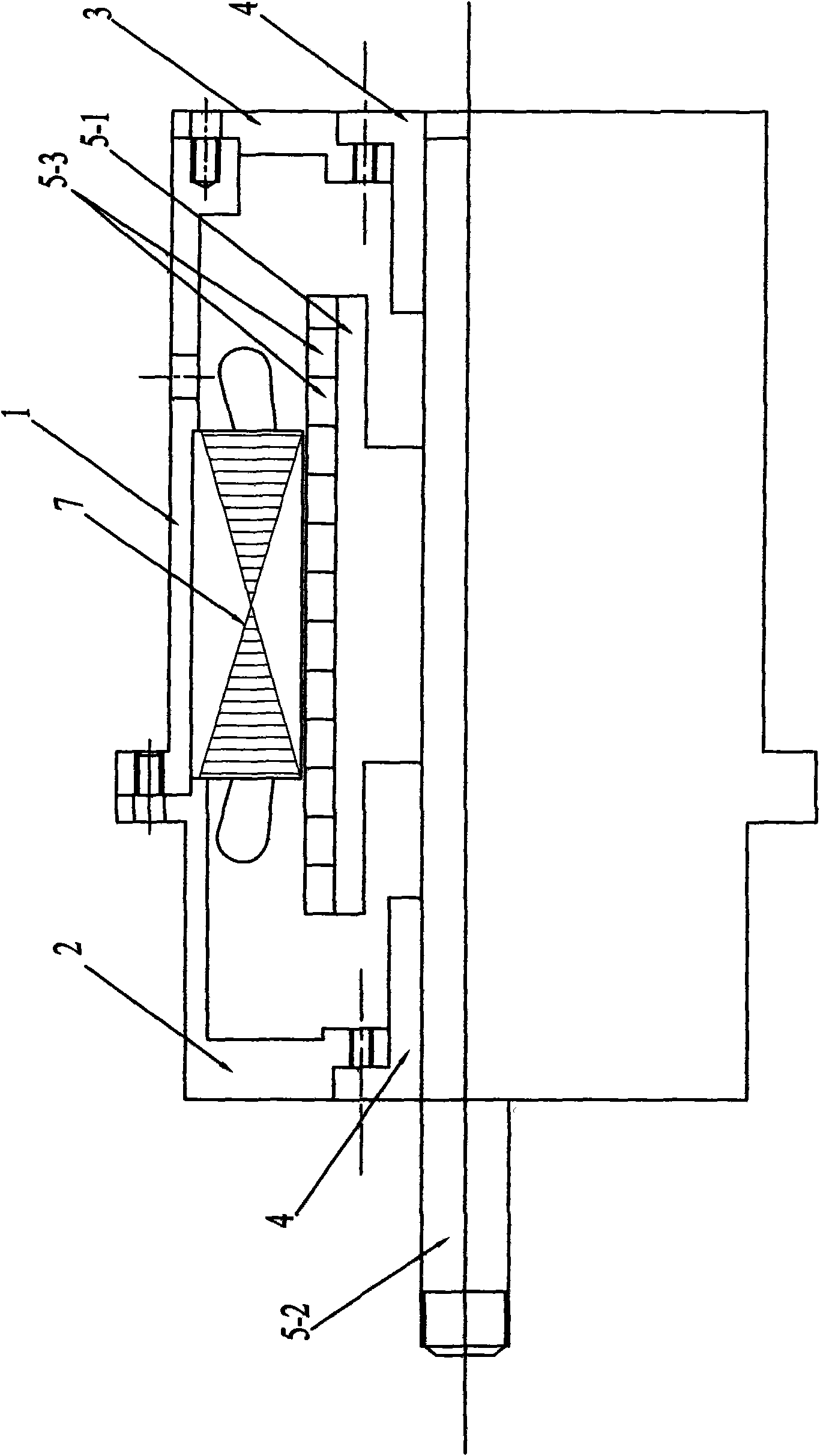
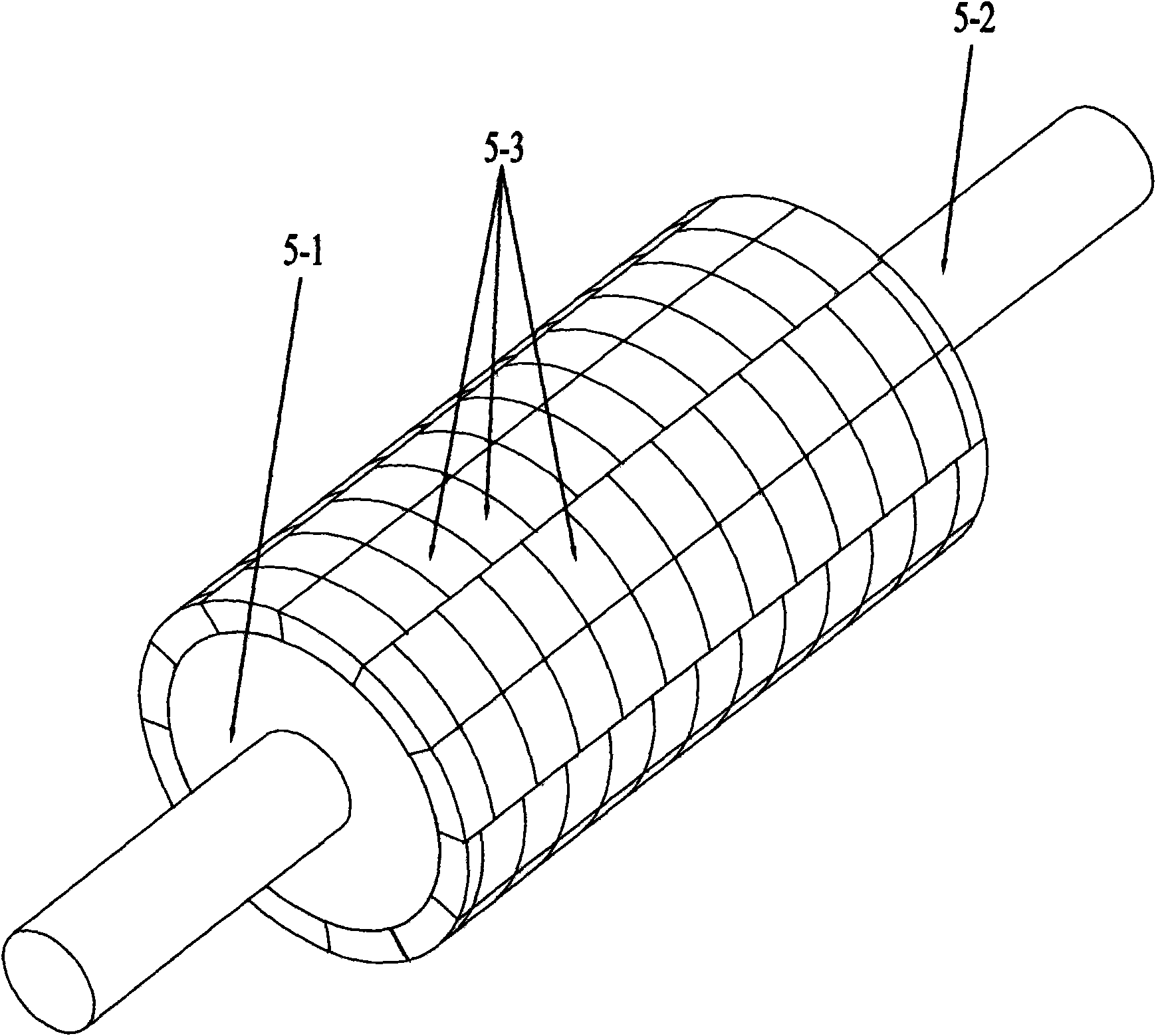
[0008] Specific implementation mode one: combine figure 2 , image 3 , Figure 9 , Figure 10 Describe this embodiment. This embodiment is composed of a casing 1, a front end cover 2, a rear end cover 3, two linear bearings 4, a mover assembly and a stator assembly; the front end cover 2 and the rear end cover 3 are respectively connected to the casing by bolts The two ends of 1 are fixedly connected; the stator assembly is installed inside the casing 1 by means of mechanical tight fit, and the mover assembly is connected to the front end cover 2 through two linear bearings 4 installed on the front end cover 2 and the rear end cover 3 It is slidingly connected with the rear end cover 3, and there is an air gap between the mover assembly and the stator assembly; the mover assembly is composed of a cylindrical mover core 5-1, a mover shaft 5-2 and a plurality of permanent magnets 5- 3 components; the mover shaft 5-2 is set through the center of the cylindrical mover core 5-1...

specific Embodiment approach 2

[0009] Specific implementation mode two: combination Image 6 Describe this embodiment, the first difference between this embodiment and the specific embodiment is that the magnetically conductive core ring 6-1 is a split type iron core with a polar arc coefficient equal to 1, that is, the magnetically conductive core ring 6-1 is the number and cylindrical A split iron core composed of I-shaped stator teeth 6-1-1 with the same number of permanent magnet bars on the outer circumferential surface of the mover iron core 5-1. Other compositions and connection methods are the same as those in Embodiment 1.

specific Embodiment approach 3

[0010] Specific implementation mode three: combination Figure 8 Describe this embodiment, the difference between this embodiment and the specific embodiment is that the magnetically conductive core ring 6-1 is a split type iron core with a polar arc coefficient less than 1, that is, the magnetically conductive core ring 6-1 is a A split iron core composed of I-shaped stator teeth 6-1-1 with the same number of permanent magnet bars on the outer circumferential surface of the sub-iron core 5-1, and two I-shaped stator teeth 6-1-1 opposite to the permanent magnet bars of each phase 1-1 Integral structure, there is a gap between two stator teeth consisting of two I-shaped stator teeth 6-1-1 of an integral structure opposite to each adjacent two-phase permanent magnet strip. Other compositions and connection methods are the same as those in Embodiment 1. This structure can eliminate the coupling between the phases.


PUM


Abstract

The invention provides a multiphase transverse magnetic field permanent magnet linear synchronous motor, which relates to a linear synchronous motor and aims to solve the problems that the prior transverse magnetic field motor has a complex structure and higher processing technological requirement. A stator component consists of n magnetic iron core rings, n-1 non-magnetic support rings and armature windings, wherein the n magnetic iron core rings and the n-1 non-magnetic support rings are arranged and overlaid alternately along the axial direction to prepare a stator core, the armature windings are encircled on I-shaped stator teeth of the magnetic iron core rings along the axial direction, the outer surface of a cylindrical mover iron core is provided with permanent magnet strips which have the same number with the pole number of motors and consist of permanent magnets along the axial direction, and the adjacent two-phase permanent magnet strips are arranged at a distance which is 2 / m times of the staggered polar distance Tau, wherein m is the phase number of the motors, and the permanent magnet strips consist of a plurality of permanent magnets which have opposite magnetization directions and are arranged alternately along the axial direction. The multiphase transverse magnetic field permanent magnet linear synchronous motor not only has simple structure and processing technique, but also has the advantages of high force density and high control characteristic, and can be widely applied in the fields of national economy, national defence and the like.

Description

technical field [0001] The invention relates to a linear synchronous motor, in particular to a transverse magnetic field linear synchronous motor. Background technique [0002] Linear motion and control systems are widely used in national economy, national defense and other fields. With the development of science and technology, higher and higher requirements are put forward for linear motion systems, including larger output to volume or weight ratio, flexible control characteristics, simple structure, and easy manufacture. There are two electric drive schemes for linear motion. One solution is to convert the rotary motion into a linear motion by using a traditional rotary motor with a lead screw. The advantage is that the design and manufacturing process of the traditional rotary motor is mature, and there are ready-made products for the screw system, so it is easy to implement and low in price. Due to the deceleration effect of the screw mechanism, the output of the syst...

Claims


Application Information

Patent Timeline
IPC IPC(8): H02K41/03H02K21/12H02K1/27
Inventor 邹继斌王骞徐永向胡建辉尚静刘承军李勇陆永平刘彦彬
Owner HARBIN INST OF TECH
Why Eureka
Try Eureka