
Rotary tillage ditching stubble burying machine capable of rotating positively and reversely

A forward-reverse, rotary tiller technology, applied in the fields of tillage equipment, agricultural machinery and equipment, application, etc., can solve the problems of inconvenient adjustment of ditch width, affecting the leveling of fields and unadjustable width, etc., and achieve the functions of installation adjustment and change. Convenience, expand the scope of use, good adaptability

Inactive Publication Date: 2009-12-23
葛伟岸
View PDF0 Cites 9 Cited by
  • Summary
  • Abstract
  • Description
  • Claims
  • Application Information

AI Technical Summary

Problems solved by technology

The disadvantages are: 1. Only one ditch can be opened at a time
Due to the limitation of cutter head speed and tractor driving speed, the forward speed of the ditching machine should not be greater than 50 m / min, otherwise there will be problems that the soil clods cut by the ditching machine are too thick to cover and the straightness of ditching is poor. Ditching at a speed below 50 m / min only requires about 10KW of power. For high-power tractors of about 50KW, there are disadvantages of energy waste and poor efficiency; 2. The width of the ditch is not easy to adjust
Since the cutter head of the ditching machine is set in the middle of the rear of the tractor, there is a barrier formed by the tractor in front and the safety of the driver is not convenient for throwing soil forward, so the ditching cutter head can only rotate forward (that is, the direction of the cutter head is backward) Rotate) to cut and throw soil clods backwards. In order to eliminate the soil clods thrown backwards from silting up in the already opened ditch, a soil clearing shovel must be installed behind the cutter head of the ditching machine, and because the width of the soil clearing shovel is difficult to match the cutter head The width of the ditching blade assembly is exactly the same as the width of the cut ditch. When the soil clearing shovel is smaller than the ditch width and depth, the residual soil in the ditch will be unclean and affect drainage; the soil cleaning shovel is wider than the ditch shape or offset in the ditch When it is on one side of the ditch, there will be scraping resistance against the ditch wall or ditch bottom, so the soil cleaning shovel must have greater rigidity and the width cannot be adjusted. The existence of the soil cleaning shovel makes it inconvenient to adjust the ditch width. China has a vast territory , Different places have different requirements for the width of the trench. For example, the width of the trench in Jiangsu and Nantong is about 15 cm, and the width of the trench in Lianyungang and Anhui is suitable for more than 25 cm. It is difficult for the existing trenchers to meet the needs of different trench widths in various places; 3. The soil clearing shovel will also accumulate the shoveled residual soil on both sides of the ditch, affecting the leveling of the field and hindering the water; 4. Due to the existence of the soil clearing shovel, the price of the ditching machine is about 3800 yuan, and the weight is about 300KG
At present, farmers need to spend more than 10,000 yuan to purchase three types of agricultural machinery: rotary tillage, stubble burying, and ditching, and it is laborious and time-consuming to replace them.

Method used


Image

  • Rotary tillage ditching stubble burying machine capable of rotating positively and reversely
  • Rotary tillage ditching stubble burying machine capable of rotating positively and reversely
  • Rotary tillage ditching stubble burying machine capable of rotating positively and reversely

Examples


Embodiment Construction

[0037] Embodiment is described in detail below in conjunction with accompanying drawing:

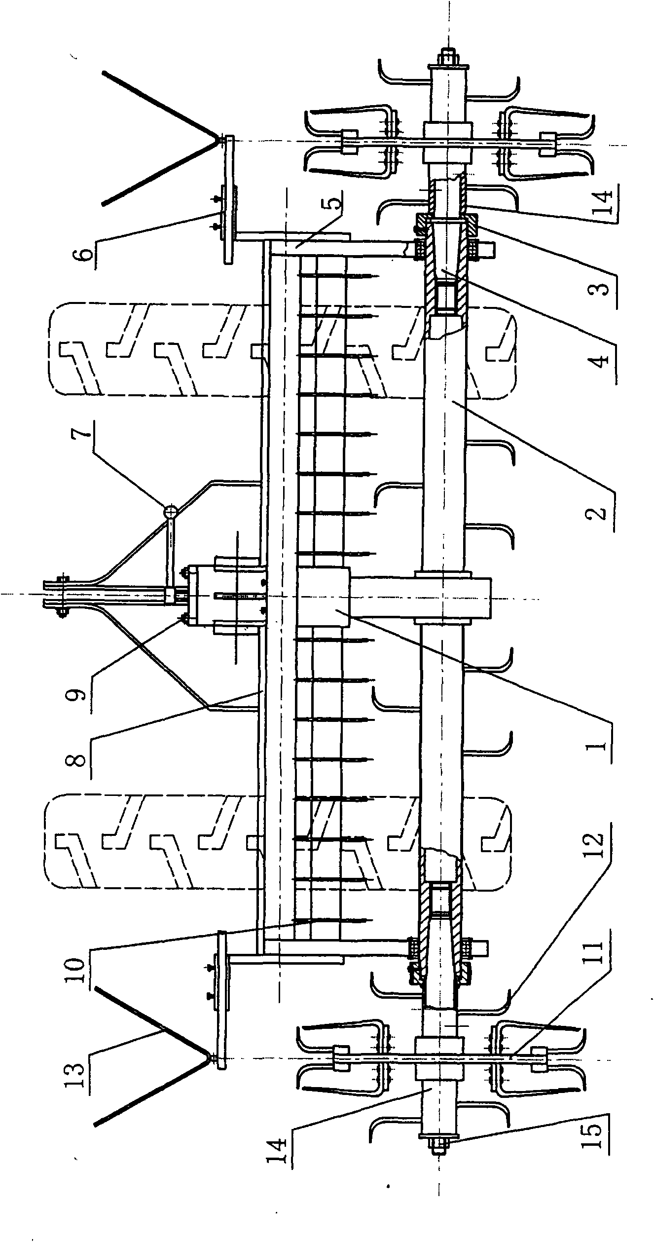
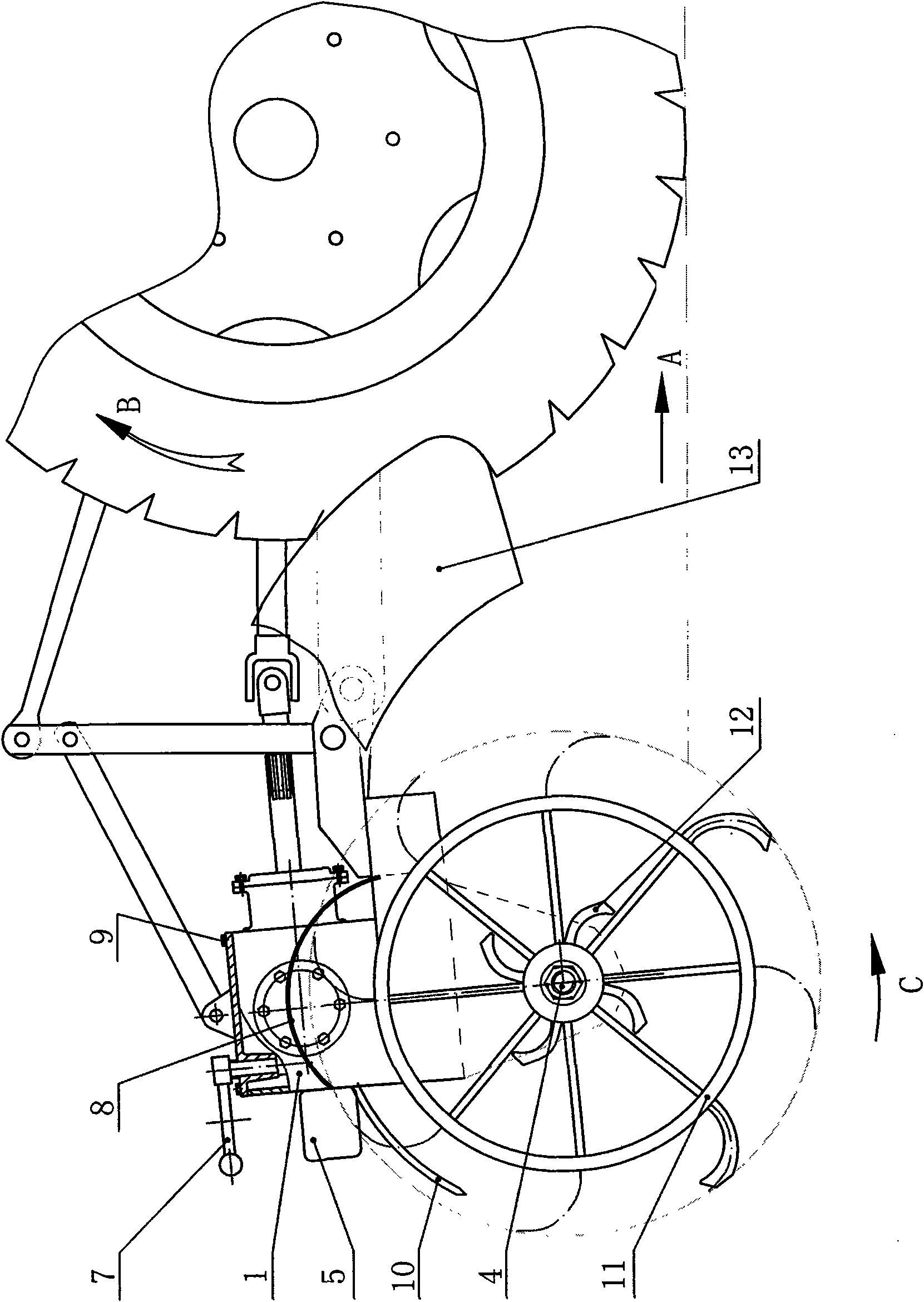
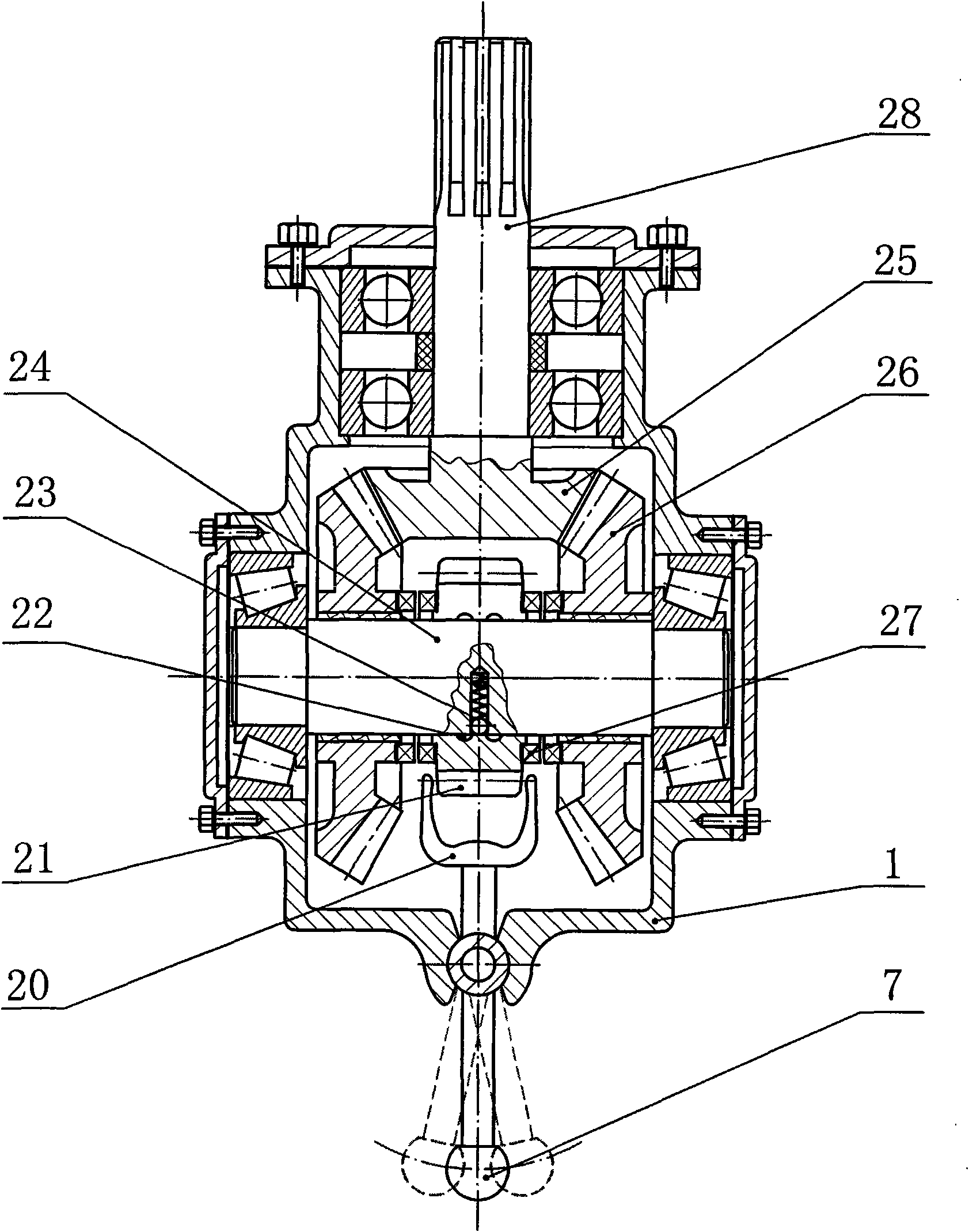
[0038] A reversible rotary tillage ditching and stubble embedding machine of the present invention, figure 1 It is the structure of Embodiment 1 shown from the rear view direction of the tractor: figure 1 Middle: 1. Reduction gear box, 2. Coulter shaft, 3. Set nut, 4. Cutter shaft, 5. Rotary cultivator frame, 6. Divider bracket, 7. Fork handle, 8. Vault Cover, 9, connecting bolt, 10, stubble fence, 11, ditching cutter head, 12, rotary tiller, 13, soil dividing plate, 14, leveling knife casing, 15, nut.

[0039] figure 1 A fork handle 7 is arranged on the upper part of the reduction gear box 1 of the rotary cultivator. The coulter shaft 2 is a circular tube structure, and the small conical end of its inner wall is provided with an internal spline. The cutter head shaft 4 is inserted into the coulter shaft 2. In the conical tube, the small conical end section is an external spline corre...


PUM


Abstract

The invention relates to a rotary tillage ditching stubble burying machine capable of rotating positively and reversely. A colter shaft of the stubble burying machine is connected with a power device of a tractor through a convertible reduction gear box of the colter shaft in positive and reverse rotating direction, and the colter shaft is provided with a rotary blade. The machine is characterized in that the left and right sides of a driven bevel gear shaft in the convertible reduction gear box in positive and reverse direction are respectively provided with a driven bevel gear, the middle of the two driven bevel gears is provided with a cylindrical gear, the two driven bevel gears are both meshed with a driving bevel gear and can both freely rotate on a driven shaft, when the driving bevel gear rotates, the two driven bevel gears do opposite rotation in different directions, the middle cylindrical gear is switched through a fork to be meshed with the jaw of the driven bevel gear at one side, and in this way, the colter shaft can rotate in positive or reverse direction. The burying stubble machine is convenient for adjustment and can change the rotating direction of the colter shaft rapidly in time according to different farmland operation needs and different usages, thus being beneficial to saving farming season and simultaneously reducing the machine purchasing cost of farmers greatly.

Description

technical field [0001] The invention belongs to the field of agricultural machinery, and in particular relates to a stubble-burying (straw returning) machine that can be expanded to have uses such as rotary tillage and ditching, and a coulter shaft and cutterhead shaft (or extension shaft) of the rotary tiller ) connection structure and a reduction gear box that can adjust the positive and negative directions of the coulter shaft. Background technique [0002] The existing farmland rotary cultivator mounted on the rear of the tractor is a model widely used in agricultural machinery with a long history. and a driven bevel gear) and several cylindrical gears to drive the rotary tiller below the coulter shaft to rotate backwards (forward rotation) to chop and plow the soil. [0003] The main disadvantage of this type of rotary tiller is that it has a single function and can only be used for fields with relatively few straws. For farmlands that need to bury a lot of rice and wh...

Claims


Application Information

Patent Timeline
IPC IPC(8): A01B33/02A01B33/08A01B33/14A01B33/12A01B33/16
Inventor 葛伟岸葛玉明
Owner 葛伟岸
Features
  • Generate Ideas
  • Intellectual Property
  • Life Sciences
  • Materials
  • Tech Scout
  • Unparalleled Data Quality
  • Higher Quality Content
  • 60% Fewer Hallucinations
Learn More