Controllable wheel-groove slow flow type water turbine/water pump

A flow-type, water-wheel technology, applied in machines/engines, rotary piston pumps, rotary piston machines, etc., can solve the problems of not easy expansion, limited energy sources, power consumption, etc., to increase output power or Water flow, wide range of energy sources, and the effect of improving work efficiency

Inactive Publication Date: 2009-12-23
李玉森
View PDF7 Cites 0 Cited by
  • Summary
  • Abstract
  • Description
  • Claims
  • Application Information

AI Technical Summary

Problems solved by technology

These two types of products generally have certain problems, which are mainly manifested in: 1. The structure of the equipment is complex. Taking a fuel engine as an example, it needs a cooling circulation system and an oil circuit system, while an electric motor requires an electrical circuit system, which will cause the cost of the product High; 2. The fuel engine will produce harmful gas due to combustion when it is working; 3. The traditional power equipment consumes a lot of power when doing work. For example, the fuel engine only has one stroke to do work in the process of 2-stroke or 4-stroke work. The remaining strokes consume power; 4. The structure of the power unit cannot be adjusted according to the requirements of the output power, resulting in a certain amount of energy waste; 5. The energy source is limited and is non-renewable
6. Traditional power equipment is heavy, bulky, low in efficiency, and not easy to expand
[0003] The use of hydroelectric power generation has the advantages of energy saving and environmental protection, but there are still some problems at present: the function is single, it can only be used as a generator, and cannot be used for other purposes; the work efficiency still needs to be improved; the impact turbine needs a large flow of water, resulting in mountain streams Small hydropower stations cannot be built in areas with small water flows, and cannot meet the electricity demand of remote mountain villages; centrifugal pumps require high speed, and the lift of centrifugal pumps is greatly affected by the speed; expansion is inconvenient

Method used


Image

  • Controllable wheel-groove slow flow type water turbine/water pump
  • Controllable wheel-groove slow flow type water turbine/water pump
  • Controllable wheel-groove slow flow type water turbine/water pump

Examples


Embodiment Construction

[0034] The present invention will be further described below in conjunction with the accompanying drawings and embodiments.

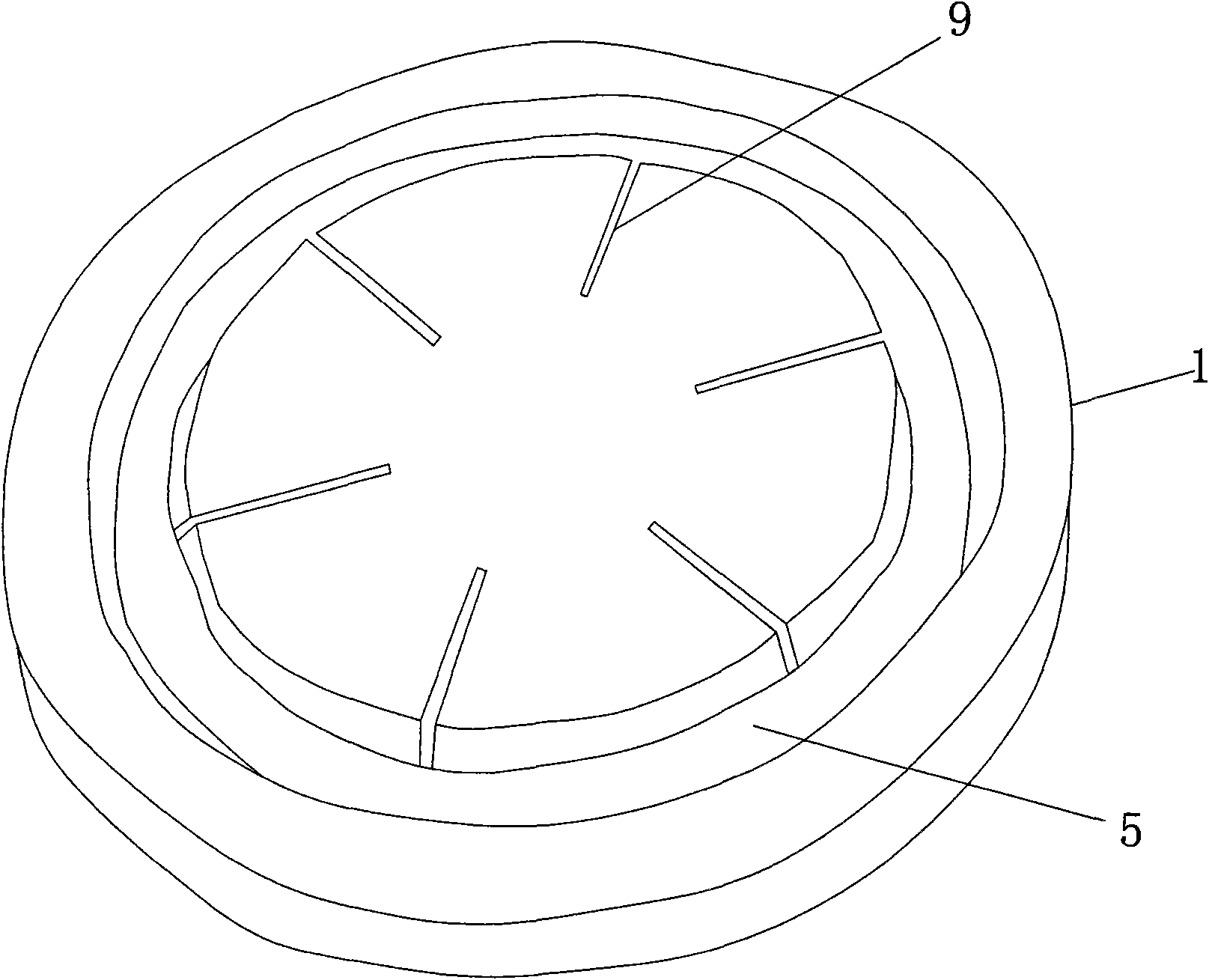
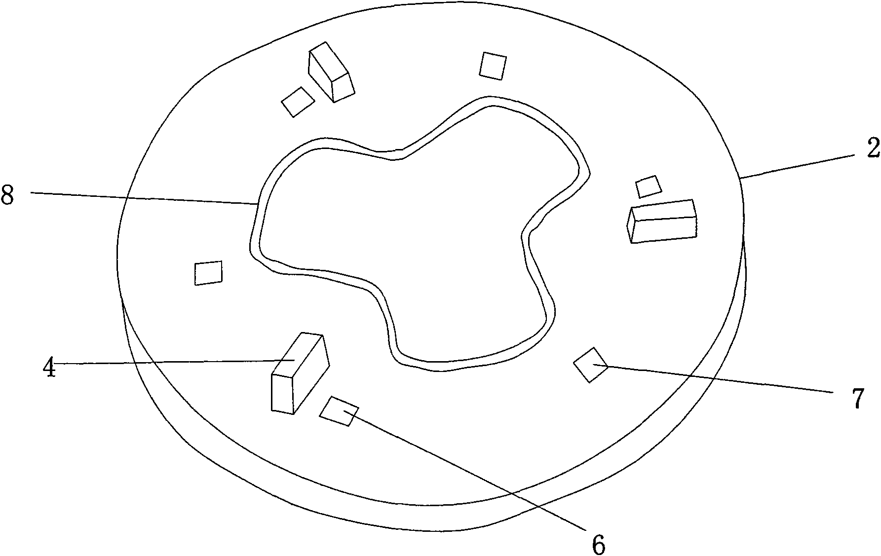
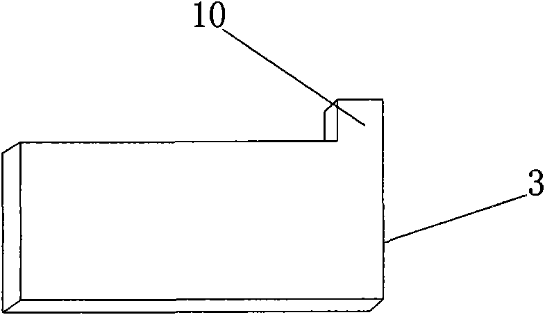
[0035] The controllable wheel groove slow-flow water wheel / water pump machine of the present invention comprises at least one hydraulic drive unit, and the hydraulic drive unit is installed on the output shaft; each hydraulic drive unit consists of a rotating wheel 1, a sealing cover 2 and a plurality of The sealing cover 2 is rotatably assembled in the water flow groove 5 of the rotating wheel 1, and the water flow groove 5 is matched with the water inlet hole 6 on the sealing cover 2. At the same time, the sealing cover 2 is also equipped with multiple The water outlet hole 7 matched with the water flow groove 5, the water inlet hole 6 is connected with the water source; a plurality of radial movable chutes 9 along the circumferential direction are also provided on the rotating wheel 1, and each sealing device is respectively arranged on the correspond...


PUM


Abstract

The invention discloses a controllable wheel-groove slow flow type water turbine / water pump, which has simple structure and convenient use, can save energy consumption and flexibly meet requirements of equipment for power, and can effectively reduce the product cost, and the like. The controllable wheel-groove slow flow type water turbine / water pump comprises at least one hydraulic driving unit which is mounted on an output shaft; each hydraulic driving unit comprises a rotating wheel, a sealing cap and a plurality of sliding sealing devices positioned between the rotating wheel and the sealing cap. The sealing cap is rotatably assembled in a water flow groove of the rotating wheel, the water flow groove is matched with a water inlet hole on the sealing cap, a plurality of water outlet holes matched with the water flow groove are arranged on the sealing cap, and the water inlet hole is connected with a water source. A plurality of radial movable sliding grooves are arranged on the rotating wheel along the circumference direction, the sealing devices are respectively arranged in corresponding movable sliding grooves and matched with wavelike moving guiding grooves at the middle part of the sealing cap.

Description

technical field [0001] The invention relates to a power output device, in particular to a controllable wheel groove slow-flow water wheel / water pump machine. Background technique [0002] Current power output devices mainly include two categories, one is to output power through a fuel engine, and the other is to output power through an electric motor. These two types of products generally have certain problems, which are mainly manifested in: 1. The structure of the equipment is complex. Taking a fuel engine as an example, it needs a cooling circulation system and an oil circuit system, while an electric motor requires an electrical circuit system, which will cause the cost of the product High; 2. The fuel engine will produce harmful gas due to combustion when it is working; 3. The traditional power equipment consumes a lot of power when doing work. For example, the fuel engine only has one stroke to do work in the process of 2-stroke or 4-stroke work. The remaining strokes...

Claims


Application Information

Patent Timeline
Patent Type & Authority Applications(China)
IPC IPC(8): F03C2/00F04C2/344F01C1/344
Inventor 李玉森
Owner 李玉森
Why Eureka
Try Eureka