Electric blower and electric duct collector equipped with the same

A technology for electric motors and blowers, applied in vacuum cleaners, machines/engines, liquid fuel engines, etc., can solve the problems of reduced reliability of electric blowers, hindering mainstream deceleration, and enlarging the interior of the blower.

Inactive Publication Date: 2009-12-23
HITACHI APPLIANCES INC
View PDF1 Cites 11 Cited by
  • Summary
  • Abstract
  • Description
  • Claims
  • Application Information

AI Technical Summary

Problems solved by technology

[0006] However, the above-mentioned series of measures for improving efficiency increase the flow velocity inside the blower, increase the aerodynamic interference force between the moving and stationary blades that become the sound source of the blade sound, and directly emit the noise from the cover to the outside, so the result It is an electric vacuum cleaner that increases the noise of the electric blower and the equipped electric blower
Moreover, in the method of providing holes in the fan cover to release the air flow, the air volume for cooling the motor is insufficient, so there is an added risk that the reliability of the electric blower will decrease.
[0007] On the other hand, in the measure of providing through-holes on the outer diameter side of the diffuser for noise reduction, although blade sound can be suppressed, the leakage air flow on the through-holes hinders the deceleration of the main flow flowing inside the diffuser, thereby reducing the Blower efficiency
[0008] In this way, efficiency improvement and noise reduction have a trade-off relationship, and it is difficult to make them coexist in the prior art

Method used


Image

  • Electric blower and electric duct collector equipped with the same
  • Electric blower and electric duct collector equipped with the same
  • Electric blower and electric duct collector equipped with the same

Examples


Embodiment 1

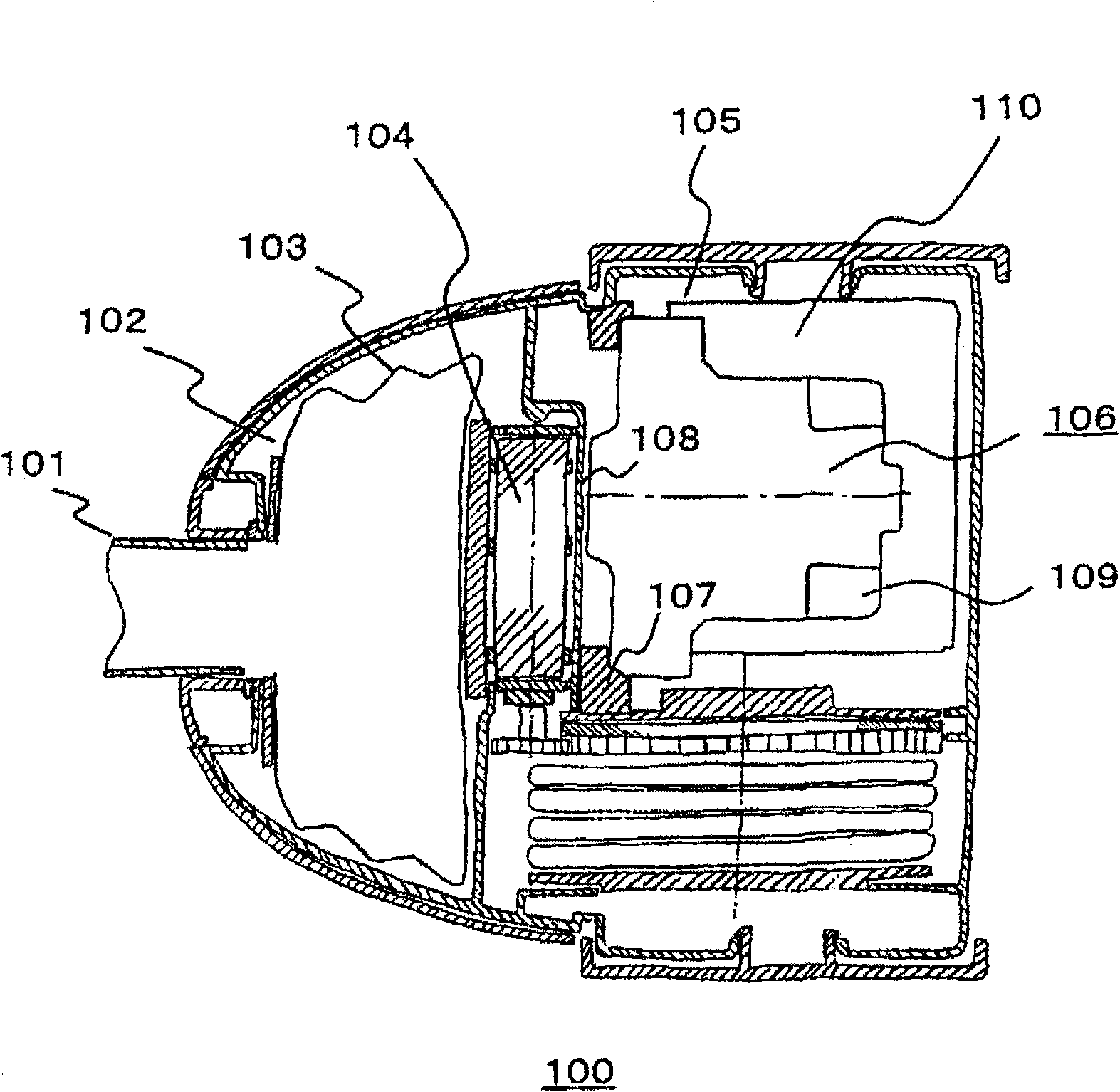
[0029] figure 1 A cross-sectional view of the main body of the vacuum cleaner showing the model. exist figure 1 , the air flow in the cleaner main body 100 will be described. A hose joint 101 is connected to the cleaner main body 100 so as to communicate with the dust collection chamber. The air flowing in from the hose joint 101 enters the dust collecting chamber 102 . exist figure 1 The paper bag 103 is shown as a dust collection unit in , and the raw material of the bag is not limited. Furthermore, in the case of the cyclone system using centrifugal separation, collection is performed in a cyclone chamber instead of the paper bag 103 . The air from which most of the dust has been removed by the paper bag 103 passes through the filter unit 104, where fine dust is also removed. Then, the airflow flows into the motor chamber 105 . The electric blower 106 is suspended in the motor chamber 105 by the anti-vibration rubber 107 , and the air flowing in from the blower inlet...


PUM


Abstract

The efficiency improvement and the noise reduce of a blower have a tradeoff selectional relation, thus it is difficult to make them to be coexisted. Therewith, the aim of the invention is to provide an electric blower having a high efficiency and a low noise, and an electric duct collector equipped with the electric blower. By means of setting through holes on most external diameter positions and a rotating center of adjacent diffuser vanes and on a diffuser still foliar in a region encompassed b a fan guard in the blower, the vane sound for dominating the noise of the blower is interfered on the surface and the back face of the foliar to be reduced, and the airflow in the diffuser is rectified in the diffuser by the control of a boundary layer of the through holes, so as to improve the efficiency.

Description

technical field [0001] The present invention relates to an electric blower and an electric vacuum cleaner equipped with the electric blower, and more particularly to a through-hole provided on a blade surface of a diffuser on the outer peripheral side of the blower. Background technique [0002] Large suction power and low noise are important requirements for electric vacuum cleaners. [0003] In order to enhance the suction force under the condition of constant power consumption, the efficiency of the electric vacuum cleaner needs to be improved, and the noise reduction of the electric blower as the sound source is also required to be quiet. Here, the blower includes a rotary centrifugal impeller as a rotor directly driven by a motor, a diffuser and a return guide as a stator. Currently, an electric blower for an electric vacuum cleaner is characterized by adopting a self-cooling method of cooling a motor using airflow generated by the blower itself. [0004] As a measure...

Claims


Application Information

Patent Timeline
Patent Type & Authority Applications(China)
IPC IPC(8): F04D17/08F04D29/44A47L5/22
Inventor 杉村和之坂上诚二本多武史常乐文夫大平房德川边拓也原田秀行
Owner HITACHI APPLIANCES INC
Why Eureka
Try Eureka