Measuring method of little opening displacement of microcrack
A technology of opening displacement and measurement method, which is applied in the field of fatigue fracture mechanics research, and can solve problems such as the accuracy and requirements of the opening displacement of few cracks, the low resolution of the opening displacement of micro-cracks, and the error of fracture performance.
- Summary
- Abstract
- Description
- Claims
- Application Information
AI Technical Summary
Problems solved by technology
Method used
Image
Examples
Embodiment approach
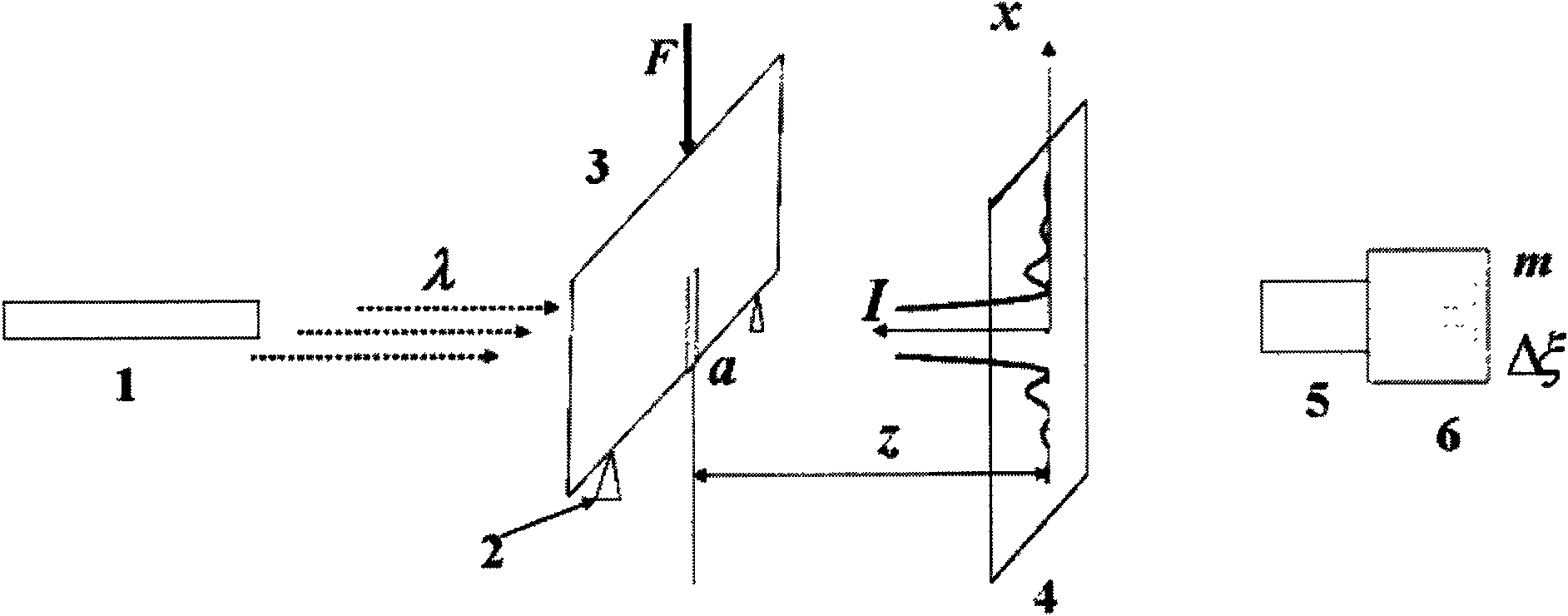
[0030] Such as figure 2 As shown, the measurement system of the microcrack opening displacement of the present invention mainly includes a laser 1, a loading device 2 (comprising a common loading frame, a force sensor, etc.), a test piece 3 with a microcrack, and a light intensity Receiving screen 4, image acquisition system 5. The system is mounted on a vibration-isolated table, and the laser emits light at a wavelength of lambda. The test piece with microcracks is placed on the loading device 2, and when the laser light passes through the microcracks, a Fraunhofer diffraction fringe pattern is formed on the light screen receiving screen 4. A slit diffraction light intensity image of the micro-crack is obtained through the image acquisition system 5, and the image is used as an initial light intensity image; the loading device 2 is used for slow loading, and the micro-crack is deformed, so that the crack is opened. At this time, through the image The acquisition camera sys...
Embodiment
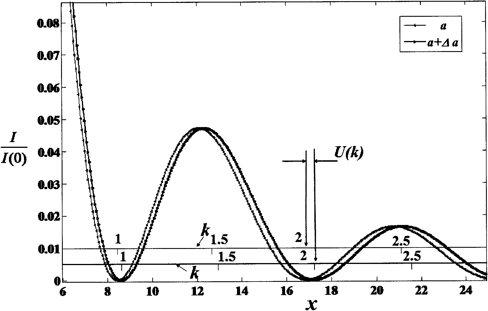
[0048] Assuming that the width of the initial tiny crack is 0.10mm, the diffraction fringe pattern obtained from the initial shooting is as follows image 3 shown. After loading, the diffraction fringes produced by the laser passing through the tiny cracks change as follows Figure 4 shown in the table. image 3 The position of the dotted line in the center is the calculated position, and the calculation process is as described in the theory. Select the position of the central point line before and after loading in the diffraction fringe as the calculation area, and perform one-dimensional digital correlation calculation on this area to obtain the result shown in the figure below, and finally perform a linear fitting on the displacement of the fringe to obtain S =0.009627, such as Figure 5 As shown. The final calculation results in ε=0.0097204, so the variation of micro cracks can be calculated as Δa=aε=0.972μm. Through the magnification of the diffraction fringe pattern,...
PUM
 Abstract
Description
Claims
Application Information
 - R&D
- Intellectual Property
- Life Sciences
- Materials
- Tech Scout
- Unparalleled Data Quality
- Higher Quality Content
- 60% Fewer Hallucinations
Browse by: Latest US Patents, China's latest patents, Technical Efficacy Thesaurus, Application Domain, Technology Topic, Popular Technical Reports.
© 2025 PatSnap. All rights reserved.Legal|Privacy policy|Modern Slavery Act Transparency Statement|Sitemap|About US| Contact US: help@patsnap.com


