Method for measuring beam intensity distribution of LED precision approach path indicator

A technology of light intensity distribution and measurement method, applied in the field of optical measurement, which can solve the problems of large deviation, slow measurement speed, and inability to achieve continuous measurement.

Inactive Publication Date: 2009-12-23
FUDAN UNIV
View PDF0 Cites 4 Cited by
  • Summary
  • Abstract
  • Description
  • Claims
  • Application Information

AI Technical Summary

Problems solved by technology

[0005] The purpose of the present invention is to provide a method for measuring the light intensity distribution of the light beam emitted by the precision approach channel indicator using LEDs, so as to overcome the large deviation caused by the current visual method judgment, and the measurement speed of the goniophotometer is slow and cannot be measured. Problems with achieving continuous measurement

Method used


Image

  • Method for measuring beam intensity distribution of LED precision approach path indicator
  • Method for measuring beam intensity distribution of LED precision approach path indicator
  • Method for measuring beam intensity distribution of LED precision approach path indicator

Examples


Embodiment

[0037] The following is the light intensity distribution of the light beam of the precision approach channel indicator used to measure the application LED of the present invention:

[0038] 1. Test process

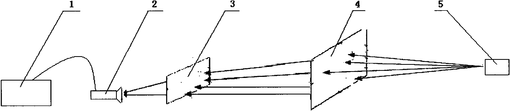
[0039] 1. If figure 1 As shown, a precision approach course indicator using red and white LEDs is placed at the position shown in the figure, and a test screen that meets the requirements is placed at a distance of 5 meters (the effective area is taken as 1.8×0.8 m 2 ), a V(λ) filter is placed several meters behind the screen along the optical path, and a CCD camera is placed behind it. It is required that the test screen and the CCD target surface are a pair of object images relative to the CCD lens, that is, the CCD can clearly Imaging test screen, the camera is directly connected to the computer;

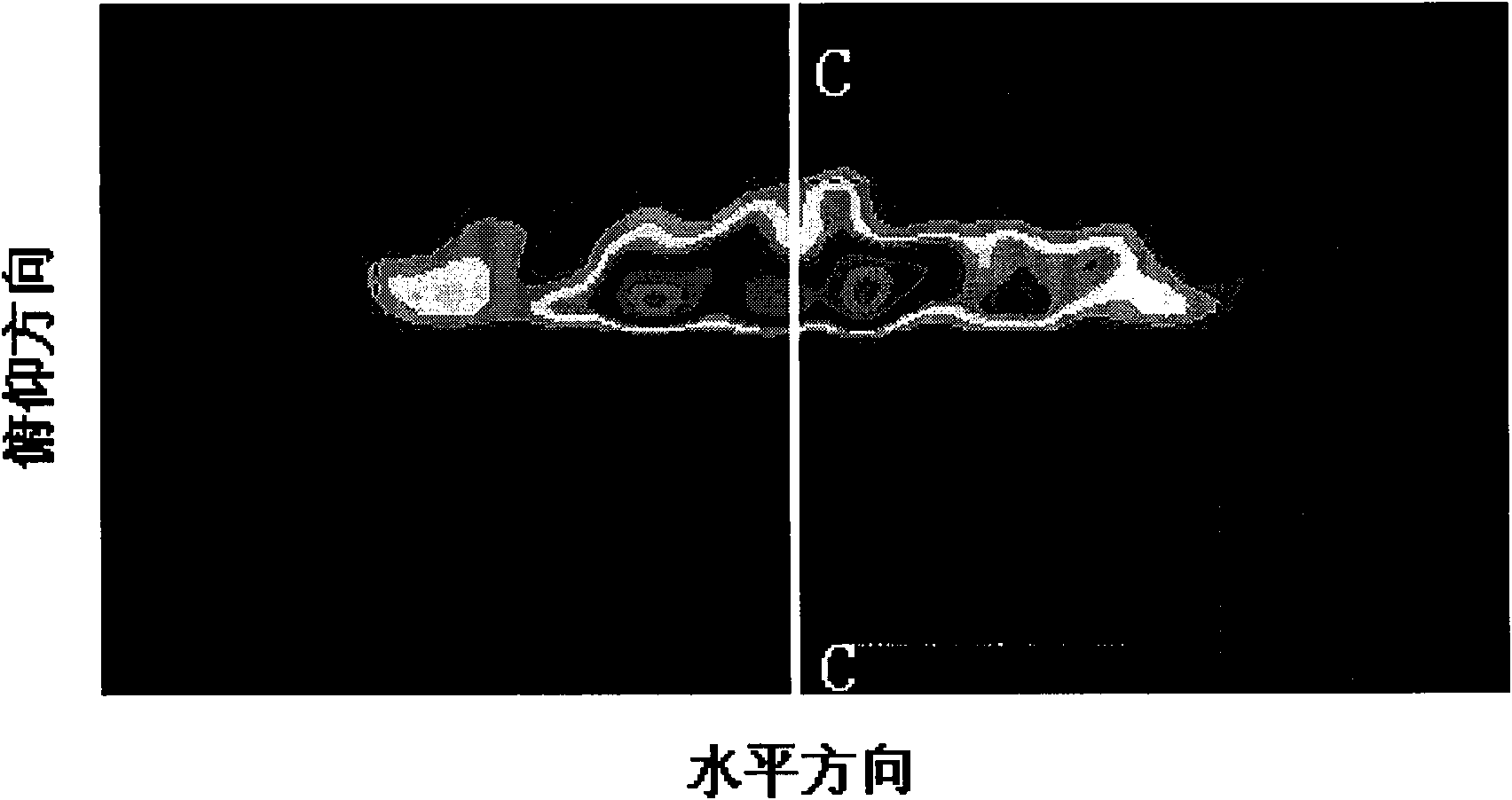
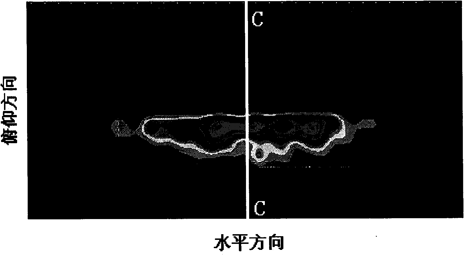
[0040] 2. Turn on the white light LED and use the CCD camera to sample the upper half of the white light beam (such as figure 2 ), and the white light beam represented b...


PUM


Abstract

The invention belongs to the field of optical measuring technologies, in particular to a method for testing the beam intensity distribution of an LED precision approach path indicator. The method comprises test system building, testing and sampling, data processing, and the like. A test system comprises an LED precision approach path indicator to be tested, a test screen, a V (lambda) optical filter, a CCD video camera and a computer. The V (lambda) optical filter and the CCD video camera are used for acquiring the gray-scale value images of two-color beams sent by the LED precision approach path indicator; and an illuminance meter is used for sampling illuminance values at a plurality of key points; and by marking illuminance values and gray-scale values, the acquired images and data are processed by a mathematical method and a computer image processing technology to obtain the intensity distribution of beams in the whole space, thereby precisely testing the intensity distribution.

Description

technical field [0001] The invention belongs to the technical field of optical measurement, and in particular relates to a method for testing the light intensity distribution of a light beam of an LED precision approach channel indicator. Background technique [0002] After the semiconductor technology triggered the microelectronics revolution, it is gestating a new industrial revolution—the lighting revolution. The characteristics of light-emitting diodes (LEDs) make them widely used in the fields of display and special lighting. In the field of aviation lamps, various lamps are gradually using LED as their light source to achieve the purpose of energy saving and emission reduction. [0003] With the rapid development of the aircraft manufacturing industry and the use of jet aircraft, the approach speed of the aircraft is getting faster and faster, and the approach time is getting shorter and shorter, so it becomes more and more important to provide pilots with accurate ap...

Claims


Application Information

Patent Timeline
Patent Type & Authority Applications(China)
IPC IPC(8): G01J1/00G06T3/00
Inventor 葛爱明魏敏晨
Owner FUDAN UNIV
Why Eureka
Try Eureka