Synchronization method for printing consumable chip data transmission

A technology for printing consumables and data transmission, applied in the field of data transmission, can solve the problems of increasing the production cost of electronic modules, unable to find a microcontroller, etc., and achieves the effect of low price and reduced production cost

Inactive Publication Date: 2011-11-30
ZHUHAI TIANWEI TECH DEV CO LTD
View PDF0 Cites 0 Cited by
  • Summary
  • Abstract
  • Description
  • Claims
  • Application Information

AI Technical Summary

Problems solved by technology

Like this, need select the microcontroller 10 that is provided with a plurality of counters 12 for use, increase the production cost of electronic module, even can't find the microcontroller 10 that is provided with suitable quantity counter 12

Method used


Image

  • Synchronization method for printing consumable chip data transmission
  • Synchronization method for printing consumable chip data transmission
  • Synchronization method for printing consumable chip data transmission

Examples


no. 1 example

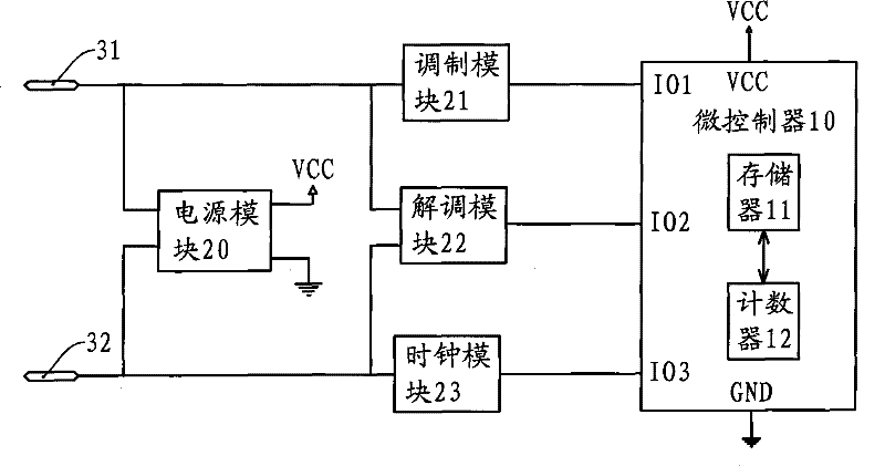
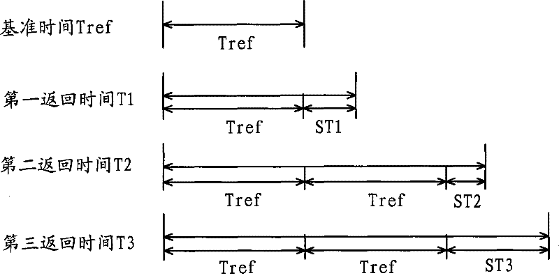
[0032] The electronic module structure of this embodiment is the same as the existing electronic module, and its electrical principle block diagram is as follows figure 1 shown, and will not be repeated here. In this embodiment, the memory 11 is set in the microcontroller 10, and stores three different response times, corresponding to three different types of information from the laser printer, that is, the microcontroller 10 receives the first type of information sent by the laser printer. information, its response time corresponds to the first return time. The schematic diagram of the division of the three return times is as follows figure 2 shown.

[0033] In this embodiment, before dividing the three return times, a reference time Tref needs to be determined. The reference time Tref is the maximum measurement value of the counter. For example, the maximum measurement value of an 8-bit counter is 256, which is 256 microseconds. After the reference time Tref is determine...

no. 2 example

[0054] see Figure 6 , is a schematic diagram of the division of the reference time and return time in the second embodiment of the present invention. Depend on Figure 6 It can be seen that, in this embodiment, the time length of the first return time T1 is shorter than the second reference time Tref2, therefore, the first return time T1 can be defined as the first reference time Tref1, that is, Tref1=T1. Each of the other return times is represented by the first return time T1 (ie, the first reference time Tref1 ), the second reference time Tref2 , and the accumulated result of the remaining time.

[0055] Depend on Figure 6 It can be seen that the second return time T2 is composed of twice the first return time T1 and the second remaining time ST2, that is, T2=1×T1+0×Tref2+ST2, so the first reference time Tref1 corresponding to the second return time T2 The set integer multiple is one time, the set integer multiple of the second reference time Tref2 is zero times, and t...


PUM


Abstract

The invention provides a method for synchronizing data transmission of printing consumable chips. The data is stored in the memory of the electronic module of the printing consumable chip. The electronic module is provided with a micro-controller which can exchange information with the outside. The return time of returning data to the outside. There is a counter in the microcontroller. The method includes determining the reference time, applying the integer multiple of the reference time setting and a remaining time accumulation result to represent the return time, and the reference time, reference time The integer multiple of the time setting and the remaining time are stored in the memory. The microcontroller judges whether the information transmitted from the outside is received. If it is to start the counter and generate the returned data, it judges the number of times the counter overflow flag is set and the integer set by the reference time. The times are equal, so the return data is sent when the counter counts to the end of the remaining time. The present invention can use the counter with fewer digits to realize the timing of the return time and reduce the production cost of the electronic module.

Description

technical field [0001] The invention relates to a method for data transmission, in particular to a synchronization method for returning and transmitting data in chips of printing consumables. Background technique [0002] Laser printers are widely used in printing work because of their advantages such as fast printing speed and good printing quality. Most existing laser printers use a detachable toner cartridge to load the toner that will be consumed during printing, and a chip is arranged on the outer wall of the toner cartridge. The chip includes a substrate, and one side of the substrate is provided with a contact for communication with the laser printer. Point, the other side is equipped with an electronic module, the electrical schematic diagram of the electronic module is as follows figure 1 shown. [0003] The electronic module includes two connection terminals 31 , 32 , a power supply module 20 , a modulation module 21 , a demodulation module 22 , a clock module 23...

Claims


Application Information

Patent Timeline
Patent Type & Authority Patents(China)
IPC IPC(8): G03G21/18H04L1/00
Inventor 谢立功
Owner ZHUHAI TIANWEI TECH DEV CO LTD
Why Eureka
Try Eureka