
Method for realizing machine tool motion control by utilizing subroutine call

A motion control and subprogram technology, which is applied in the field of machine tool motion control using subprogram calls, can solve the problems of bloated programs, time-consuming and laborious, and increase the workload of programmers, and achieve the effect of real-time modification and convenience.

Inactive Publication Date: 2009-12-23
上海奈凯电子科技有限公司 +1
View PDF0 Cites 22 Cited by
  • Summary
  • Abstract
  • Description
  • Claims
  • Application Information

AI Technical Summary

Problems solved by technology

Auxiliary functions are usually written in G code format. If you simply use G00, G01, G02, G03 and other instructions to compile step by step, the program will be tedious and cumbersome, and it is easy to make mistakes when a large number of program segments are input into the system.
At the same time, although the specific parameters in the program are different, the program structure is usually similar. If a group of program segments with the same structure repeatedly appear in the program, it will undoubtedly make the program bloated and greatly increase the workload of the programmer.
Corresponding to different but similar purposes, a large number of program codes need to be modified, which obviously does not conform to the modern software reusability mechanism
[0004] At the same time, this method makes it impossible to modify the software in real time, because according to the existing method, even if only a small change is required to the program, it must be modified in the source code, and then the new software is compiled and released, which is time-consuming and laborious.

Method used


Image

  • Method for realizing machine tool motion control by utilizing subroutine call
  • Method for realizing machine tool motion control by utilizing subroutine call
  • Method for realizing machine tool motion control by utilizing subroutine call

Examples


Embodiment Construction

[0021] In order to make the technical means, creative features, goals and effects achieved by the present invention easy to understand, the present invention will be further described below in conjunction with specific illustrations.

[0022] The method of the present invention is concrete in implementation process, and its operation environment is: numerical control software adopts C++ language to write, and corresponding editing environment is VC++, and subroutine adopts G code file format to be written in the text document, can run in WindowsXP and Windows2000.

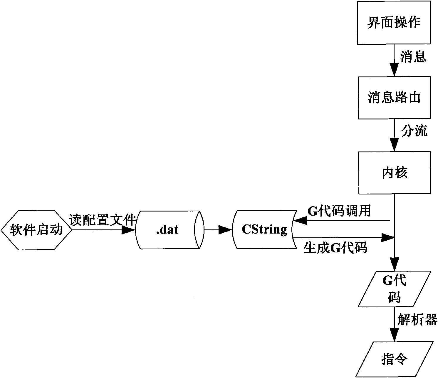
[0023] see figure 1 , the specific implementation steps are:

[0024] 1: the G code subroutine text file (usually .ini, .dat file, which is set to .dat file in the present invention) provided by the machine tool manufacturer. The .dat file is placed under the specified folder target.

[0025] 2: When the system starts, the main program first reads the .dat file into the cache, saves the CString structure, and enca...


PUM


Abstract

The invention discloses a method for supporting the real-time correction to functions in a machine tool auxiliary motion control system of a highly-custom mechanism. The method comprises the following steps: writing a corresponding machine tool motion operation auxiliary control G-code routine into a subroutine format that is commonly used in a numerical control system; building all subroutines into an independent function library; making a .dat configuration file; and calling the corresponding G-code subroutine by a master routine while implementing the machine tool action. The invention enables that corresponding numerical control machine tools with different specifications and similar functions do not need to correct a numerical control software source code, and only need to correct corresponding subroutine function configuration files. The functions can be corrected directly in real time by a machine tool operator according to respective specific using conditions so as to match the actual environment. The invention has the advantages that the function and the realization of the machine tool action are separated, and the corresponding G code is not stored in the master routine and implemented in a free calling manner.

Description

Technical field: [0001] The invention relates to the field of numerical control machine tool systems, in particular to a method for realizing machine tool motion control by using subroutine calling. Background technique: [0002] Machine tools are the main production equipment in the manufacturing industry. Traditional processing equipment mostly uses special-purpose machine tools such as general-purpose machine tools and combined machine tools. With the progress of society, people have higher and higher requirements for various products. Some products with high complexity and precision requirements need to use advanced flexible production lines to replace traditional rigid production lines. CNC machine tools just meet these requirements. In recent years, my country's numerical control technology has developed very rapidly, and the penetration rate of numerical control machine tools has also become higher and higher. In particular, popular machine tools with functions that ...

Claims


Application Information

Patent Timeline
IPC IPC(8): G05B19/18G05B19/4155
Inventor 郑之开赵东京
Owner 上海奈凯电子科技有限公司
Learn More