Adjustable eccentric transmission device for machine tool, in particular for superfinishing or honing

An eccentric transmission and guiding device technology, which is applied in the direction of superfinishing machines, honing machines, grinding drives, etc., can solve the problems of time-consuming adjustment or change, inability to affect and optimize surface quality, high cost, etc., and achieve high efficiency The effect of structural form

Inactive Publication Date: 2009-12-30
SUPFINA GRIESHABER
View PDF0 Cites 11 Cited by
  • Summary
  • Abstract
  • Description
  • Claims
  • Application Information

AI Technical Summary

Problems solved by technology

As a result, adjusting or changing the stroke of the reciprocating motion is very time-consuming and cost-intensive
[0005] Furthermore, it is not possible

Method used


Image

  • Adjustable eccentric transmission device for machine tool, in particular for superfinishing or honing
  • Adjustable eccentric transmission device for machine tool, in particular for superfinishing or honing
  • Adjustable eccentric transmission device for machine tool, in particular for superfinishing or honing

Examples


Example Embodiment

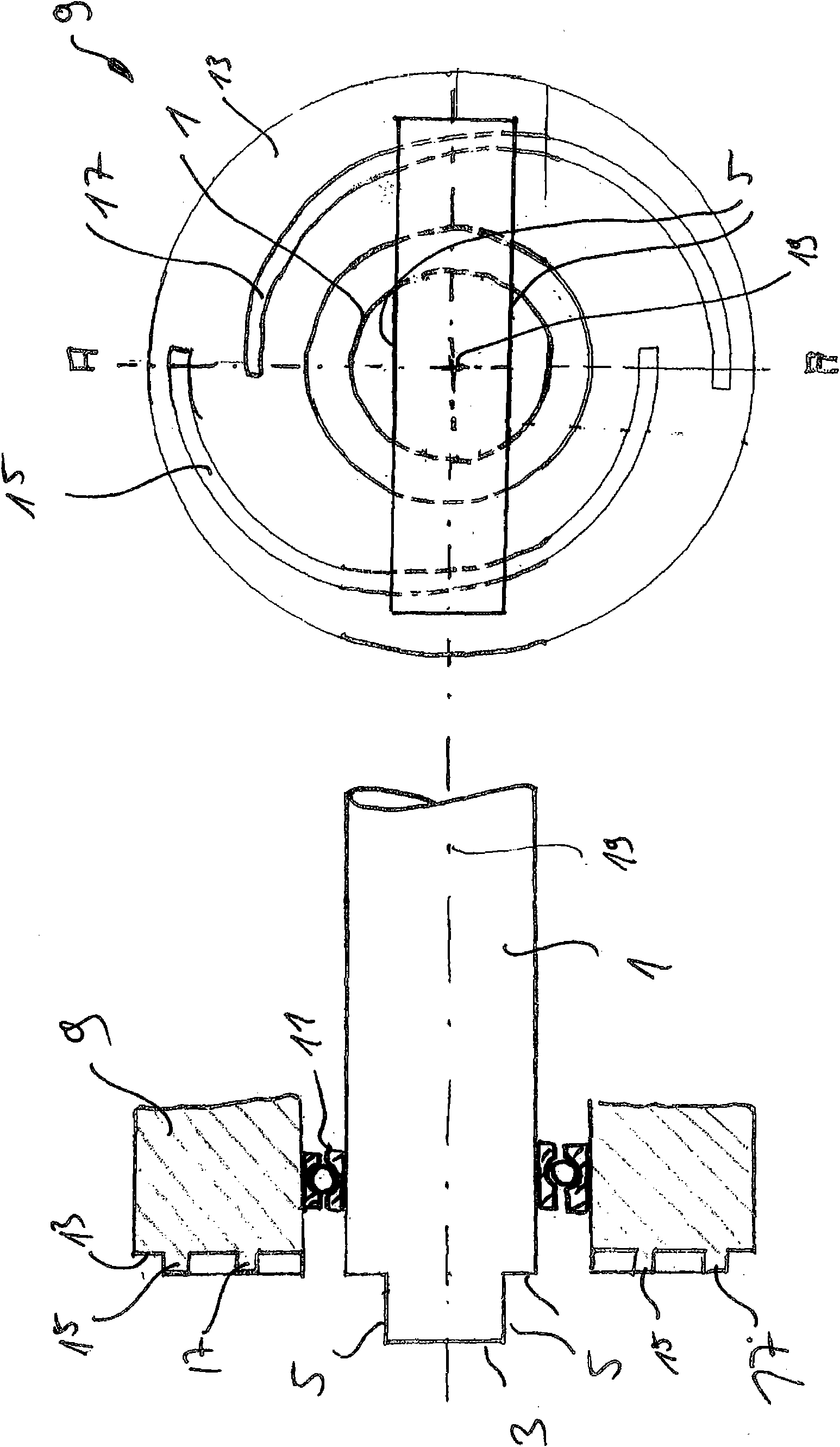
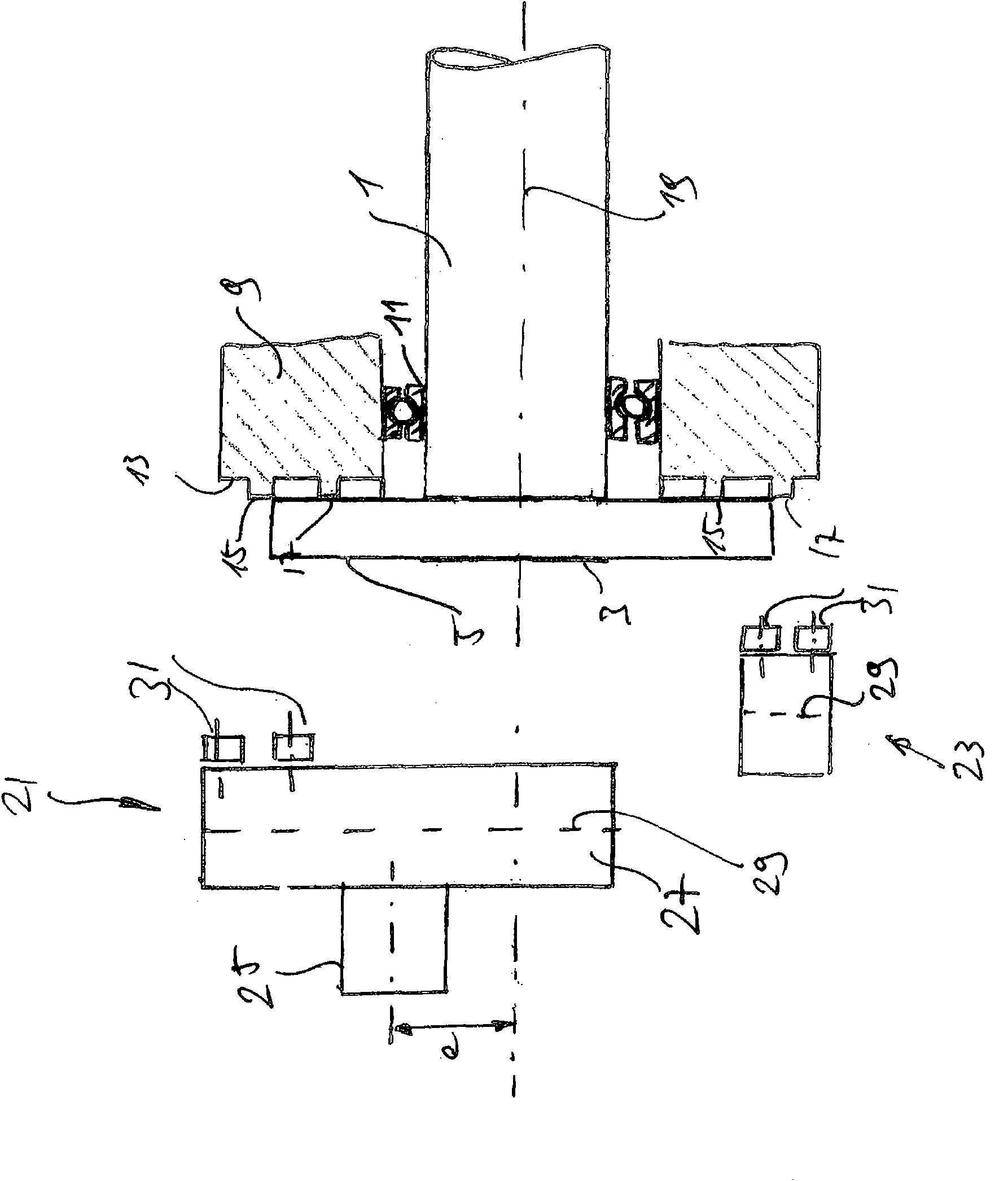
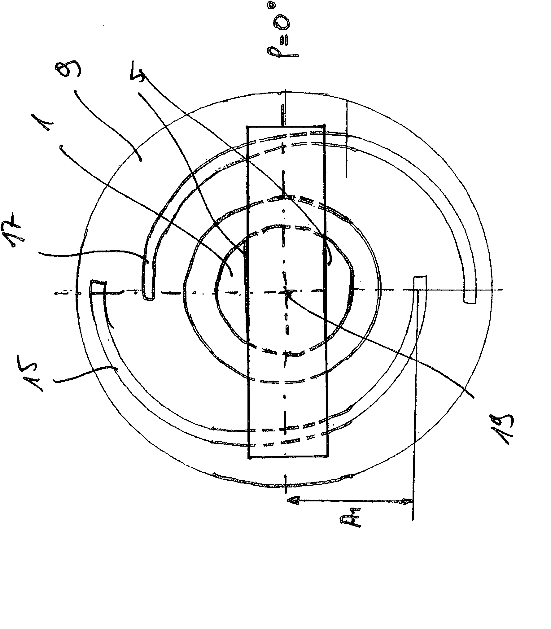
[0029] The figure shows a first axis 1 . The first shaft 1 is mounted rotatably in a housing, not shown. A linear guide 5 is formed on one end face 3 of the first shaft. A bearing 11 is arranged between the adjusting ring 9 and the first shaft 1 . This means that the setting ring 9 is rotatable relative to the first shaft 1 . One end face 13 of the setting ring 3 has a first guide rib 15 and a second guide rib 17 . The guide ribs 15 and 17 are helical within the scope of the invention, since the distance of the guide ribs from the axis of rotation 19 of the first shaft 1 is angle-dependent. exist figure 1 In the exemplary embodiment shown, the helical ribs 15 and 17 are designed as arc segments which are arranged eccentrically with respect to the axis of rotation 19 . However, it is also possible to design the helical ribs 15 and 17 as Archimedean or logarithmic spirals. It is also possible to design the lift of the helix to be related to the angle.

[0030] When the ad...


PUM


Abstract

The invention relates to an adjustable eccentric transmission device, wherein the travel of a cylindrical crank pin (21) can be definitely adjusted when a main shaft (1) is running. The eccentric transmission device is in particular applicable for the following machine tools in which cutting tools carry out reciprocating movement with different travels.

Description

technical field [0001] The invention relates to an adjustable eccentric drive for machine tools for superfinishing or honing. Background technique [0002] In various cutting operations, such as superfinishing, honing, upset forging and planing, the tool performs a reciprocating (oscillating) movement. In this case, a crank pin arranged on the shaft at a distance A from the axis of rotation is usually actuated in order to convert the rotational movement of the electric drive into the desired reciprocating movement. [0003] Since the stroke of the reciprocating motion is mainly related to the workpiece, it is desirable that the stroke of the crank pin be adjustable. [0004] The possibility of forming an adjustment has so far only existed for stationary tools. As a result, adjusting or changing the stroke of the reciprocating movement is very time-consuming and cost-intensive. [0005] Furthermore, it has not been possible to specifically influence and optimize the qualit...

Claims


Application Information

Patent Timeline
IPC IPC(8): B24B35/00B24B33/00B24B47/16
CPCB24B23/04B23Q5/027B24B47/12B24B35/00B23D7/10B24B33/10F16C3/28F01L1/344F16C2322/39
Inventor 于尔根·罗泽
Owner SUPFINA GRIESHABER
Why Eureka
Try Eureka