Bottom-blown air brick of top and bottom repeatedly blown converter and installing structure thereof

A converter bottom blowing, top and bottom combined blowing technology, applied in the manufacture of converters, etc., can solve the problem of blockage and short melting of bottom blowing air bricks, so as to ensure air permeability, improve service life, and solve the problems of blockage or short melting

Inactive Publication Date: 2011-02-16
SHANDONG IRON & STEEL CO LTD
View PDF1 Cites 1 Cited by
  • Summary
  • Abstract
  • Description
  • Claims
  • Application Information

AI Technical Summary

Problems solved by technology

[0004] Aiming at the defects of the prior art, the present invention provides a top-bottom re-blowing converter bottom-blowing air brick and its installation structure, which can promote the rapid generation of "slag-metal mushroom head" on the top of the bottom-blowing air brick in the initial stage of new furnace production, Ensure air permeability, so as to solve the problem of blockage or short melting of the bottom blowing brick, and realize the synchronization of the life of the bottom blowing brick and the furnace lining in the whole furnace

Method used


Image

  • Bottom-blown air brick of top and bottom repeatedly blown converter and installing structure thereof
  • Bottom-blown air brick of top and bottom repeatedly blown converter and installing structure thereof
  • Bottom-blown air brick of top and bottom repeatedly blown converter and installing structure thereof

Examples


Embodiment 1

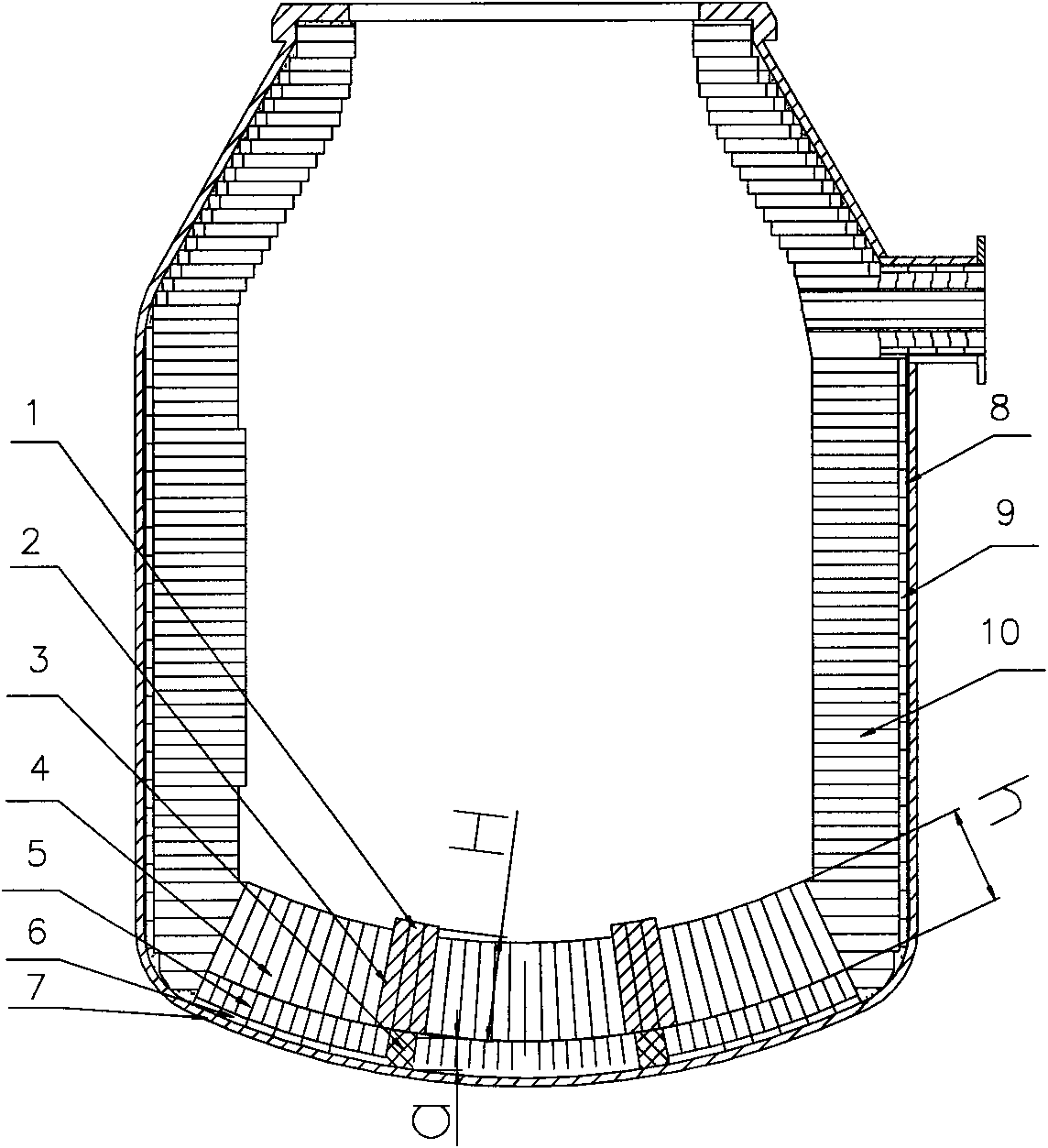
[0020] Such as figure 1 As shown, a top-bottom re-blowing converter bottom-blown air-permeable brick is composed of an air-permeable brick 1, an air-permeable brick seat brick 3 and two protective bricks 2, the protective brick 2 is located on both sides of the air-permeable brick 1, and the air-permeable brick seat brick 3 is located The lower part of the breathable brick 1, and the center hole is aligned up and down.

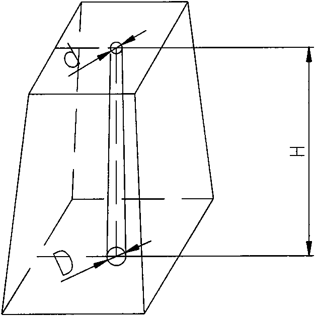
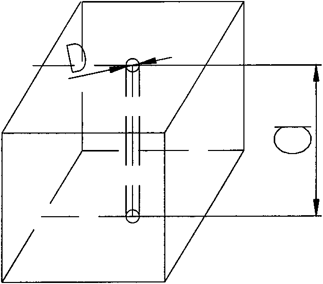
[0021] Such as figure 2 As shown, the materials of the breathable brick 1 and the protective brick 2 are both magnesia carbon, the grade is MT-18AA, the physical and chemical indicators are: MgO: 74.86%, C: 18.89%, bulk density: 2.96g / cm3, significantly Porosity: 2.98%, compressive strength at room temperature: 39.83Mpa, flexural strength (1400°C×0.5h): 12.4Mpa; breathable brick 1 and protective brick 2 have the same dimensions, both of which are wedge-shaped with trapezoidal surfaces. The lower two faces are rectangular, and the front, back, left, and righ...

Embodiment 2

[0025] Others are the same as in Example 1, except that the lower aperture D of the permeable brick 1 is 26 mm, and the upper aperture d is 24 mm.

[0026] The central aperture D of the air-permeable brick seat brick 3 is 26mm. Bottom blowing ventilation brick 1 and both side protection bricks 2 are 110mm higher than furnace bottom working lining magnesia carbon brick 4.


PUM

PropertyMeasurementUnit
densityaaaaaaaaaa
compressive strengthaaaaaaaaaa
flexural strengthaaaaaaaaaa

Abstract

The invention relates to a bottom-blown air brick of top and bottom repeatedly blown converter and an installing structure thereof, which are mainly characterized in that two sides of the bottom-blown air brick are respectively laid with a protective brick, the height H of the bottom-blown air brick and the protective brick is more 80-120 mm than that h of a bottom working liner magnesia carbon brick, the shape size of the bottom-blown air brick is the same with the shape size of the protective bricks at two sides of the bottom-blown air brick, and the protective bricks and the bottom-blown air brick are tread gauged bricks. The invention can promote slag-metal cupping at the top of the bottom-blown air brick during the production primary period of a new converter to be rapidly produced, thereby solving the problem of blockage or burning-out of the bottom-blown air brick, ensuring the air permeability, and greatly prolonging the service life of the bottom-blown air brick, wherein the service life of the bottom-blown air brick reaches more than 20,000 furnaces. The layout structure of the air brick strengthens the mixing of molten steel in a molten pool, quickens elements in the molten pool to mutually generate the chemical reaction, and remarkably reduces the content of TFe in the slag, wherein the content of the TFe averagely reaches below 15 percent.

Description

technical field [0001] The invention belongs to the technical field of iron and steel metallurgy intermediate converter steelmaking process, and mainly relates to a top-bottom double-blowing converter bottom-blowing ventilation brick and its installation structure. Background technique [0002] In recent years, the top-bottom compound blowing technology of converters has been widely promoted and applied, but the life of the bottom-blown air bricks has not reached the requirement of synchronizing with the life of the furnace lining. It will be blocked, and the reblowing ratio of 100% cannot be realized, and the technical advantages of reblowing steelmaking in the whole furnace cannot be fully utilized. Through the application test, it is found that the bottom blowing effect and the life of the air brick have a great relationship with the installation layout and structural design of the bottom blowing air brick. In terms of the installation structure of the ventilation brick,...

Claims


Application Information

Patent Timeline
Patent Type & Authority Patents(China)
IPC IPC(8): C21C5/44
Inventor 吕铭武光君李洪建
Owner SHANDONG IRON & STEEL CO LTD
Why Eureka
Try Eureka