Position control method for vibration attenuation and apparatus thereof

A technology of positioning control and feedback control, which is applied in the direction of mechanical oscillation control, non-electric variable control, control/regulation system, etc., can solve the problem of deviation between the model and the actual action, and achieve the effect of improving the vibration stop accuracy and reducing the response characteristics

Active Publication Date: 2009-12-30
IHI CORP
View PDF2 Cites 11 Cited by
  • Summary
  • Abstract
  • Description
  • Claims
  • Application Information

AI Technical Summary

Problems solved by technology

[0013] However, when applying this characteristic to an actual device, the parameters need to be adjusted because the mod

Method used


Image

  • Position control method for vibration attenuation and apparatus thereof
  • Position control method for vibration attenuation and apparatus thereof
  • Position control method for vibration attenuation and apparatus thereof

Examples


Embodiment Construction

[0056] Next, preferred embodiments of the present invention will be described with reference to the drawings. In addition, in each figure, the same code|symbol is attached|subjected to the common part, and overlapping description is abbreviate|omitted.

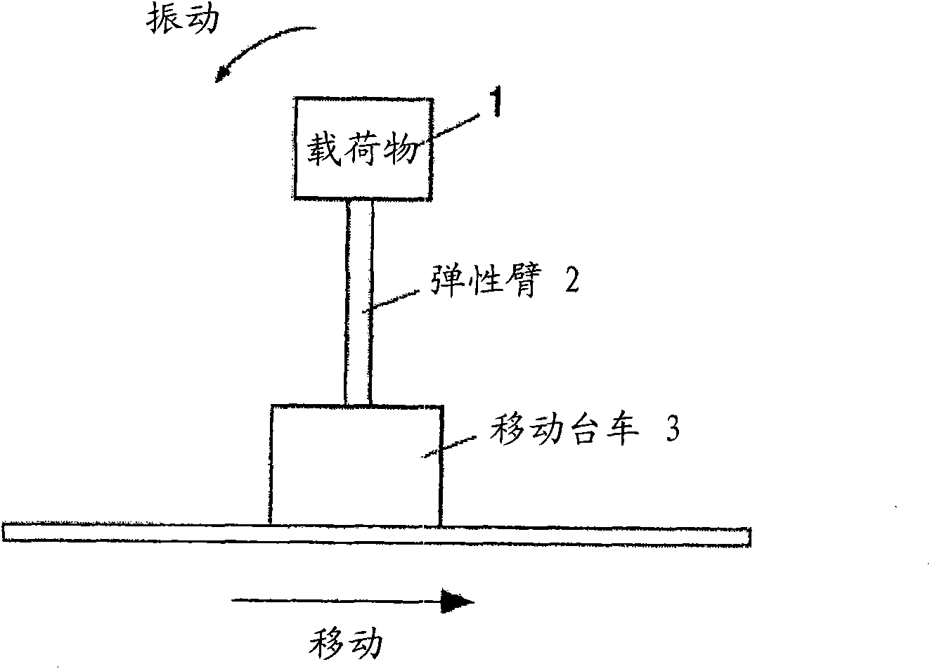
[0057] Figure 4 yes image 3 A model diagram of the moving body shown. In this mobile object model, a load 1 with a mass m is fixed to a mobile cart 3 via an elastic arm 2 with a length L. As shown in FIG.

[0058] Here, k is the coefficient of elasticity, θ is the angle, M is the mass of the trolley, f is the driving force, and g is the acceleration due to gravity.

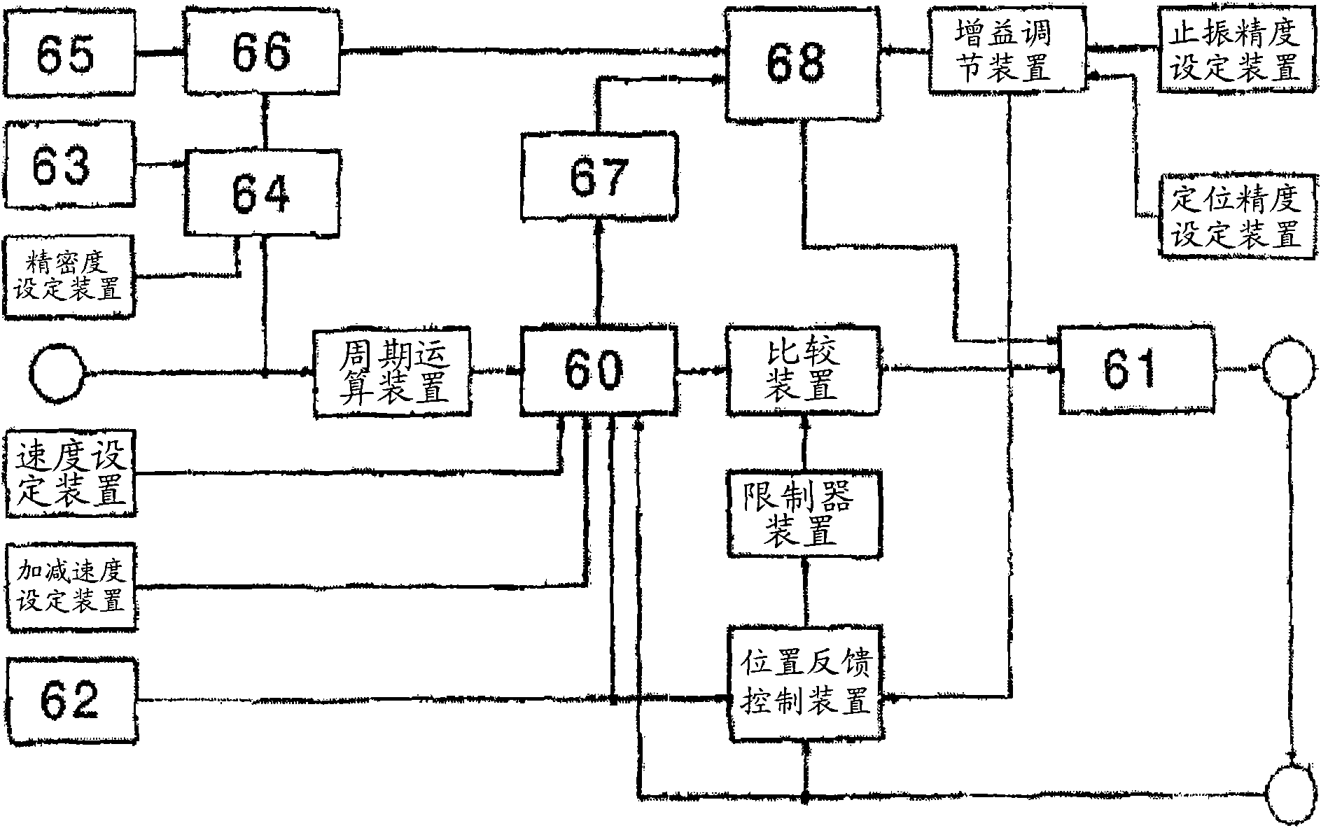
[0059] Furthermore, the mobile trolley 3 calculates the state variable (described later) of the measuring load 1 in real time by means of the vibration damping positioning control device 10 of the present invention, and performs feedback control in a closed loop.

[0060] The kinetic energy V of this model is expressed by the formula (1) of the number 1, and...


PUM


Abstract

A position control method for vibration attenuation and an apparatus thereof are provided. It is unnecessary to measure actual movement and parameter adjustment to reduce number of vibration during acceleration/deceleration period without generating vibration greater than static vibration generated by acceleration to reduce stress generation; it is unnecessary to set the number of vibration randomly by corresponding the acceleration/deceleration period with a natural period. The position control method for vibration attenuation and apparatus inhibit vibration of a mobile body with vibration or elastic deformation during acceleration/deceleration to position. Vibration of the mobile body is modeled by a spring-particle system with single-degree-of-freedom to solve the natural period of themodel so that the acceleration graph during acceleration/deceleration is trapeziform graph comprising constant speed increasing and decreasing of the acceleration and so that constant time of each acceleration is of integral multiple to the natural period to set the acceleration graph. The acceleration graph controls movement of the mobile body and detects state variables of the mobile body. The mobile body is feedback controlled according to a deviation of a target value of state variable generated by the acceleration graph and a current value of the state variable detected.

Description

technical field [0001] The invention relates to a vibration damping positioning control method and device, which are used for correct positioning by suppressing the vibration of a moving body that vibrates or elastically deforms during acceleration / deceleration. Background technique [0002] Mobile objects such as cranes and manipulators, which have a structure that tends to vibrate or elastically deform during acceleration / deceleration, vibrate back and forth or elastically deform during movement, making accurate positioning difficult. Therefore, Patent Documents 1 and 2, for example, have proposed methods of computing and measuring such a moving body in real time, suppressing vibration by closed-loop control, and performing positioning. [0003] The object of Patent Document 1 is to achieve vibration damping and high-precision positioning of the suspension when reaching a target point. [0004] For this, as figure 1 As shown, the control system is the anti-vibration cont...

Claims


Application Information

Patent Timeline
IPC IPC(8): G05D19/02
Inventor 铃木俊太郎
Owner IHI CORP
Why Eureka
Try Eureka