

EPON video camera
A camera and optical image technology, applied in the field of EPON cameras, can solve the problems of restricting the large-scale popularization and application of high-definition IP cameras, IP network congestion, complex system equipment, etc., to achieve direct long-distance optical fiber networking, increase transmission bandwidth, and increase costs Effect
- Summary
- Abstract
- Description
- Claims
- Application Information
AI Technical Summary
Problems solved by technology
Method used
Image

Examples
Embodiment Construction
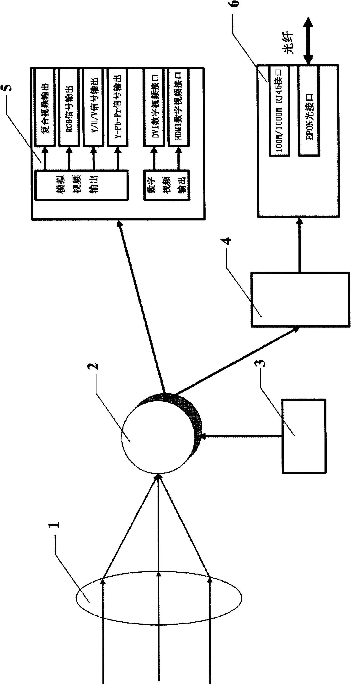
[0020] see figure 1 , this embodiment is composed of a lens 1, an image sensor module 2, a controller 3, a video compression coding module 4, an analog / digital video output interface module 5, and an EPON ONU module 6. The output end of the controller 3, the lens 1 is connected with the input end of the image sensor module 2, the input end of the video compression encoding module 4, the analog / digital video output interface module 5 is connected with the output end of the image sensor module 2, and the EPONONU module The input end of 6 is connected with the output end of video compression coding module 4. in:
[0021] Lens 1 adopts the optical lens of prior art;
[0022] Image sensor module 2 adopts MT9T031 CMOS digital image sensor, which has 3 million pixels and a maximum resolution of 2048X1536;
[0023] The controller 3 uses an ordinary single-chip microcomputer to program and control the MT9T031 CMOS digital image sensor;
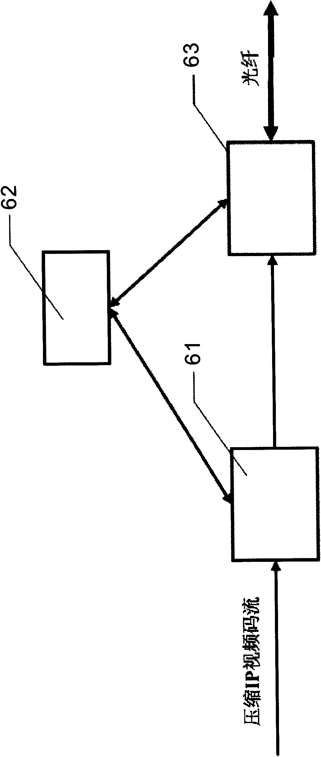
[0024] Video compression coding module 4 ado...
PUM
 Abstract
Description
Claims
Application Information