Commercial LED illumination driver

A LED lighting and driver technology, applied in the field of driving circuits, can solve the problem of mining the quality of the power grid of LED driving circuits without considering the overall efficiency improvement and service life of LED light source driving circuits, and propose a complete solution without LED lighting driver design. The service life has not reached the expected value, etc., to achieve the effects of variable scene effects, improved energy efficiency, and long service life

Active Publication Date: 2009-12-30
GUANGZHOU FUDAN AUTO SCI & TECH
View PDF0 Cites 52 Cited by
  • Summary
  • Abstract
  • Description
  • Claims
  • Application Information

AI Technical Summary

Problems solved by technology

At present, the research on LED lighting driver is still in its infancy, and the research focus of various manufacturers is mostly on the development of LED driver chip itself, and no complete solution has been proposed for the design of LED lighting driver.
Judging from the currently known LED lighting driver design schemes, none of them consider the overall efficiency improvement of the LED light source drive circuit, the excavation of the service life and the impact of the LED drive circuit on the quality of the power grid. The power factor compensation has not been considered when the LED light source is applied in the lighting field. Problems such as the impact of harmonics on the power grid are capacitive loads, and their power factor is only 0.5-0.57, which greatly reduces the transmission efficiency of the power grid. According to the requirements of the electrical design code for civil buildings, the power factor of electrical equipment should be above 0.85 be qualified
Since the LED drive circuit must complete the

Method used


Image

  • Commercial LED illumination driver
  • Commercial LED illumination driver
  • Commercial LED illumination driver

Examples


Embodiment Construction

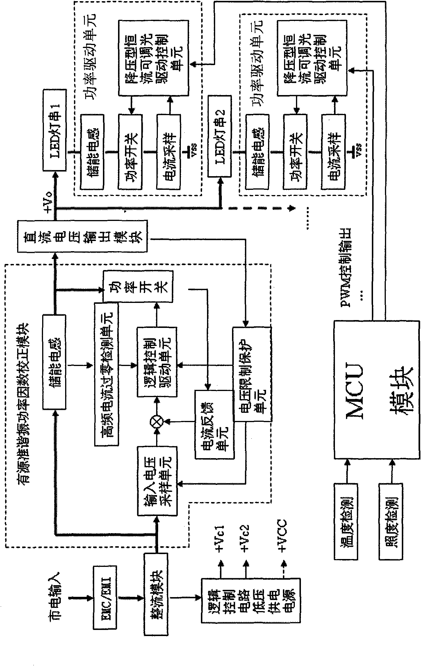
[0026] refer to figure 1 , figure 2 , a commercial LED lighting driver of the present invention, which includes

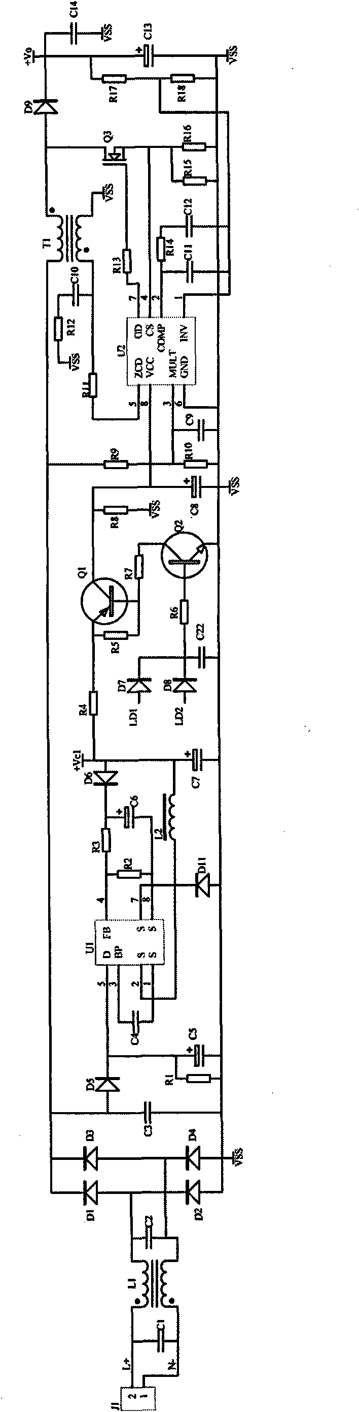
[0027] The electromagnetic filter module is EMC / EMI in the present invention, and its input end is connected to the power grid input, which can suppress and absorb the harmonics generated by the LED driver, so as not to affect the power grid quality; It is composed of filter capacitors C1 and C2 at both ends. Due to the quasi-resonant active power factor correction scheme, the harmonic influence of the drive on the grid is very small. Therefore, simple capacitor filtering and inductor harmonic suppression can achieve good EMC / EMI power grid quality control indicators.

[0028] The rectifier module, whose input end is connected to the output end of the electromagnetic filter module, rectifies and filters the input current, and is composed of rectifier diodes D1, D2, D3, D4 and filter capacitor C3 that form a bridge rectifier.

[0029] The active quasi-resonant ...


PUM


Abstract

The invention discloses a commercial LED illumination driver. The driver comprises a rectifier module, an active quasi-resonant power factor correction module and a direct current voltage output module; wherein the input terminal of the rectifier module is connected with commercial power system, so as to rectify and filter input current; the input terminal of the active quasi-resonant power factor correction module is connected with the output terminal of the rectifier module, so as to inhibit harmonic wave produced by the LED driver and compensate the power factor; and the terminal of the direct current voltage output module is connected with the output terminal of the active quasi-resonant power factor correction module, so as to provide working voltage for LED string light. The invention applies an active power factor correction circuit working in quasi-resonant mode to LED illumination driver design and realizes substantive improvement on LED illumination driver power factor. The power factor of the LED illumination driver is improved from 0.5-0.57 to more than 0.99, harmonic wave quality index of the power system is contained in detailed design of the LED illumination design, and waveform coefficient of the LED illumination driver is improved from about 2 to below 1.2.

Description

technical field [0001] The invention relates to a driving circuit, in particular to a commercial power LED lighting driver. Background technique [0002] Electric light source lighting has experienced three generations of incandescent lamps, fluorescent lamps, and high-intensity gas discharge lamps. The light efficiency has been continuously improved, and the power consumption has been continuously reduced. The light of electricity has played a vital role in the development of human society. Today, due to the advancement of semiconductor technology, another new electric light source, LED light-emitting diode, replaces the traditional electric light source with comprehensive advantages such as energy saving, environmental protection, longevity, reliability, small size, various colors, flicker resistance, and anti-vibration. Set off the fourth revolution in the lighting industry. Many manufacturers have noticed the broad prospects of light-emitting diodes in the field of ligh...

Claims


Application Information

Patent Timeline
IPC IPC(8): H05B37/02H02M7/04H02M1/42
CPCY02B70/126Y02B70/10
Inventor 陈迪泉钱静钟卓鹏
Owner GUANGZHOU FUDAN AUTO SCI & TECH
Why Eureka
Try Eureka