
2D-dimming of illuminating member for display device

A component and display technology, applied in optics, nonlinear optics, static indicators, etc., can solve problems such as large additional costs, achieve the effect of maintaining image quality and reducing manufacturing costs

Inactive Publication Date: 2009-12-30
KONINK PHILIPS ELECTRONICS NV
View PDF1 Cites 1 Cited by
  • Summary
  • Abstract
  • Description
  • Claims
  • Application Information

AI Technical Summary

Problems solved by technology

For dimming the active display part, the dimming is typically made dependent on the image content and the lighting is split into many segments to obtain a satisfactory image quality, thereby incurring considerable additional costs

Method used


Image

  • 2D-dimming of illuminating member for display device
  • 2D-dimming of illuminating member for display device
  • 2D-dimming of illuminating member for display device

Examples


Embodiment Construction

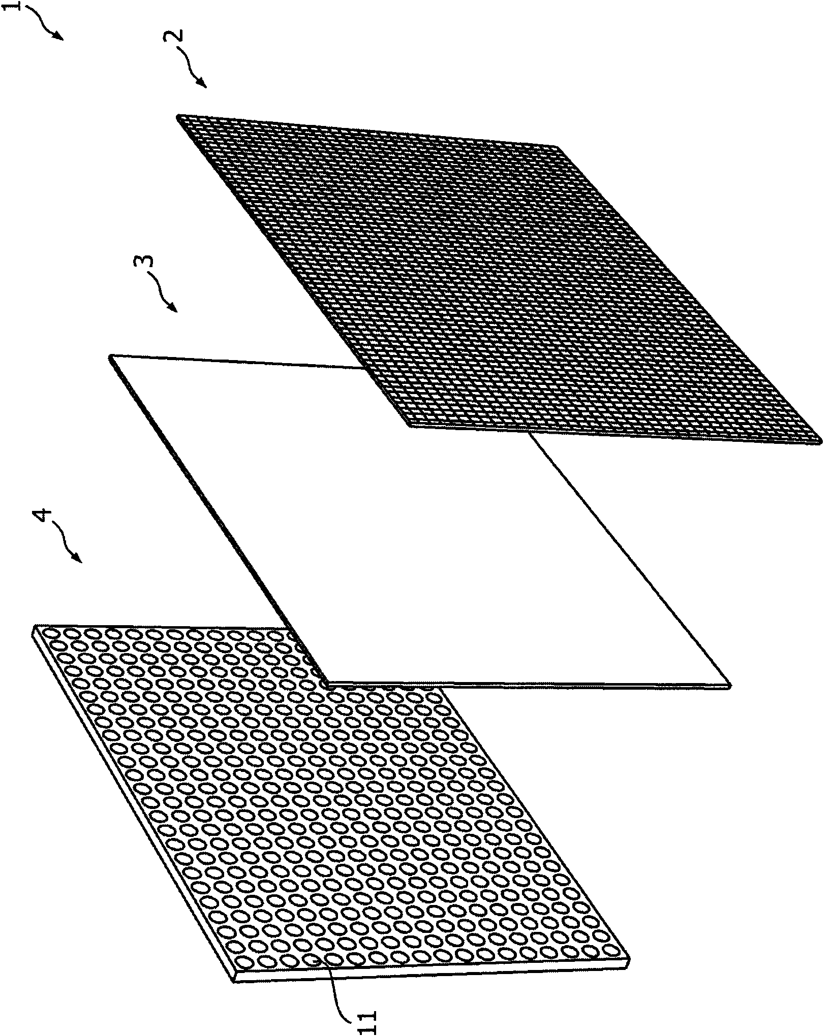
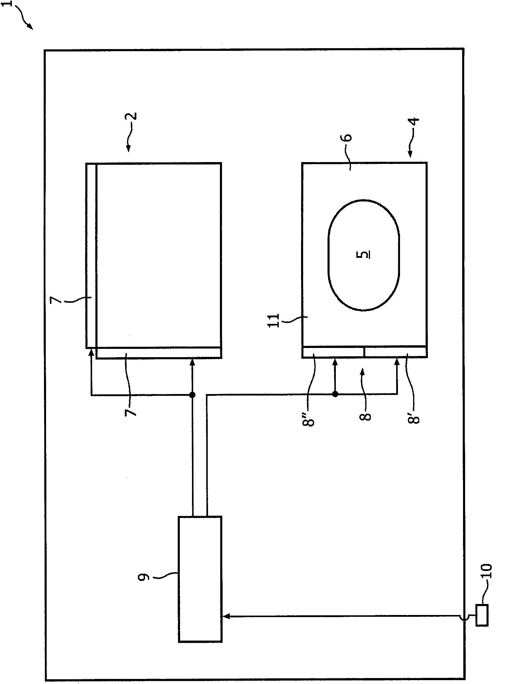
[0039] Figure 1-2 is a schematic diagram of a display 1 according to an embodiment of the invention. The display 1 includes an illumination member 4 and a display panel 2 . In this example, the lighting member 4 is arranged behind the display panel 2 and is thus called a backlight. The backlight 4 may have a plurality of light emitting elements 11 . Light emitting elements 11 can be red (R), green (G) and blue (B) light emitting diodes (LEDs), while alternative embodiments may utilize phosphor-converted white light from the LEDs (either on-die or phosphor conversion on the lens) or from a remotely located plate. The backlight 4 may be connected to a controller 9 through an illumination driving circuit 8 .

[0040] Such as figure 1 As shown, the display 1 may also include an optical system 3 between the backlight 4 and the display panel 2 . The optical system 3 comprises eg a diffuser plate and / or a brightness enhancement foil and / or other optical plates or sheets, which...


PUM


Abstract

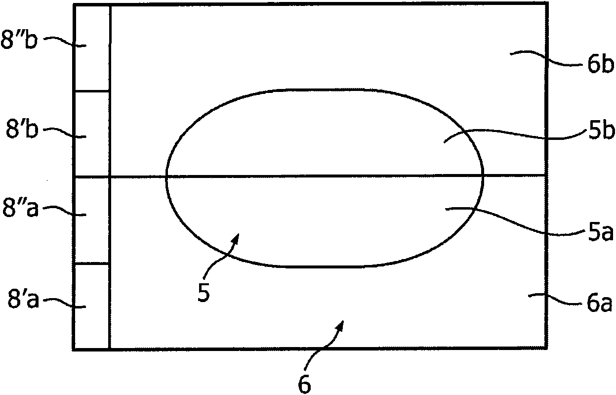
An illuminating member (4) that, independent of any image content, comprises a central region (5) and an enclosing region (6), wherein said enclosing region (6) is adapted to emit light of lower quality than the light emitted by the central region (5). The illuminating member is adapted to illuminate a display panel (2) of a display device. Byhaving the enclosing region emit light of lower brightness (dimming) a significant power reduction can be achieved for a wide range of typical images while largely maintaining the perceived image quality. Further, byusing light emitting elements of lower quality for the enclosing region, manufacturing costs may be reduced while largely maintaining the perceived image quality.

Description

technical field [0001] The invention relates to an illumination member for illuminating a display panel to generate an image. Background technique [0002] Currently, dimming of display panel lighting is widely used in electronic devices (such as MP3 players, mobile phones, portable computers, and TVs). For displays requiring high performance, improved dynamic contrast and reduced power consumption can be achieved by segmenting the illumination of the display panel into segments and controlling dimming for each segment based on the corresponding image content. However, this is associated with a considerable cost penalty, since each segment requires its own driver circuit and additionally an additional LED power supply must be installed in order to be able to boost the LEDs to compensate for the loss of adjacent dimmed segments. Brightness contribution. Such systems are thus generally too expensive to be used in eg consumer TVs. [0003] In EP 1 653 435 a more cost effecti...

Claims


Application Information

Patent Timeline
Patent Type & Authority Applications(China)
IPC IPC(8): G09G3/34G02F1/13357
CPCG09G3/3426G02F1/133603G09G2320/066G09G2320/062G09G2330/021G02F2001/133614G09G2320/0626G09G2360/144G02F1/133614G02F1/1335G09G3/34
Inventor J·P·雅各布斯R·范沃登伯格E·H·A·兰根迪克M·H·R·兰克霍斯特G·哈伯斯
Owner KONINK PHILIPS ELECTRONICS NV
Learn More