

Method and apparatus for laser soldering
一种激光焊接、激光的技术,应用在激光焊接设备、送锡装置、辅助装置等方向,能够解决电子零部件4烧损、导电不良、外观不良等问题,达到消除烧损问题的效果
- Summary
- Abstract
- Description
- Claims
- Application Information
AI Technical Summary
Problems solved by technology
Method used
Image

Examples
Embodiment Construction
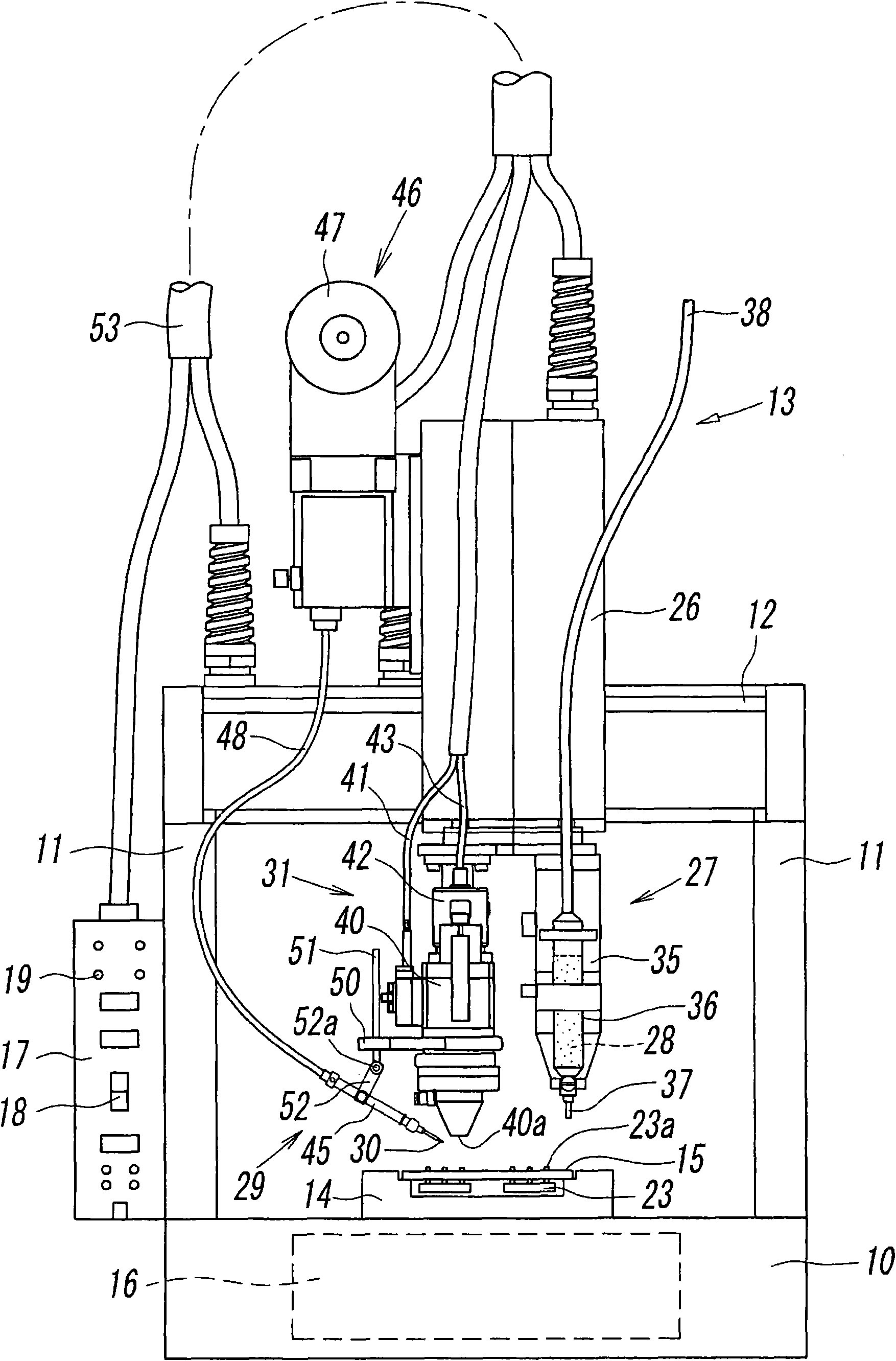
[0024] figure 1 It is a figure which shows one Embodiment of the laser welding apparatus of this invention. The laser welding device automatically performs welding according to the set program, including: a welding platform 10 with a rectangular top view shape; a pair of supporting columns 11 arranged at the left and right ends of the welding platform 10; horizontally spanning between the upper ends of the supporting columns 11 The guide rail 12; the welding head 13 that can move laterally (X direction) along the guide rail 12; the substrate support table 14 that is arranged on the described soldering station 10 for carrying the printed circuit board 15 as the welding object. The substrate supporting table 14 is operable to move in the front-back direction (Y direction) of the soldering table 10 .
[0025] Inside the soldering station 10, a control device 16 for controlling the action of the entire device is built in, and an operation panel 17 is provided on the side of the ...
PUM
 Abstract
Description
Claims
Application Information