Headwind horizontal drier

A technology of drying machine and drying fan, which is applied in the direction of progressive drying machine, drying machine, drying solid materials, etc. It can solve the problems of slow drying speed, inability to achieve uniform drying, and small heating area of ​​workpieces, so as to improve drying speed, The effect of increasing the heating area and increasing the evaporation rate

Inactive Publication Date: 2010-01-06
杭州景生木业机械有限公司
View PDF1 Cites 5 Cited by
  • Summary
  • Abstract
  • Description
  • Claims
  • Application Information

AI Technical Summary

Problems solved by technology

Its disadvantages: firstly, due to the use of circular air nozzle point drying or divergent hot air drying, the goal of

Method used


Image

  • Headwind horizontal drier

Examples


Embodiment 1

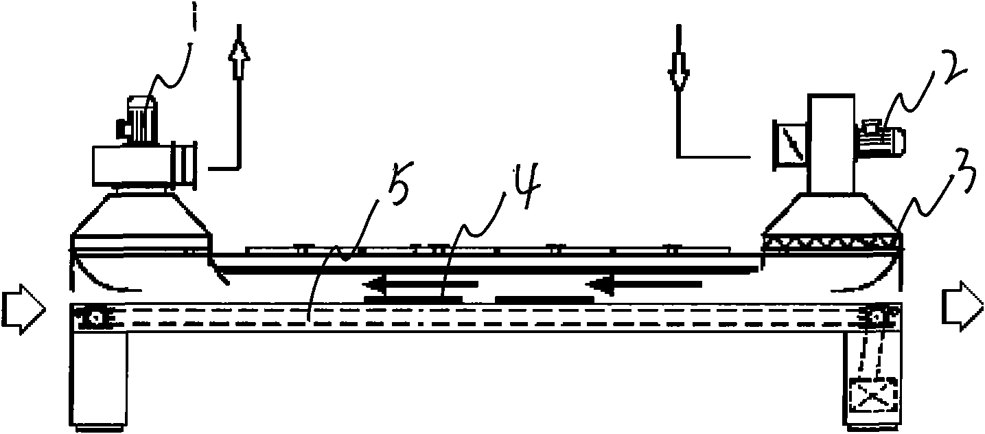
[0008] Embodiment 1: with reference to attached figure 1 . Upwind horizontal dryer, which includes a dryer, one end of the dryer is provided with an inlet fan 2, and the other end is provided with an outlet fan 1, and the wind direction is opposite to the conveying direction of the workpiece 4, between the inlet fan 2 and the dryer There is heating and filter 3 between the air ducts, and heating and filter 3 are made of heater and filter, and filter is positioned at the rear portion of heater. The force generated by the wind speed in the wind direction is less than the adhesion force of the painted surface.


PUM


Abstract

The invention relates to a headwind horizontal drier which comprises a drier, wherein one end of the drier is provided with an air inlet fan, the other end of the drier is provided with an air outlet fan, and the wind direction is opposite to the transmitting direction of a workpiece. The headwind horizontal drier has the advantages that one end of the drier is provided with the air inlet fan, the other end of the drier is provided with the air outlet fan, the wind direction is opposite to the transmitting direction of the workpiece, the flowing speed of air is relatively improved, the evaporating speed of water in paint is improved, the heated area of the workpiece can be increased, the drying speed of the workpiece is improved, and the workpiece is more uniformly dried; a heater and a filter are arranged between the air inlet fan and an air duct of the drier, the dust and other impurities in the fresh air absorbed into the air inlet fan can be filtered, and the filtered air can be heated.

Description

technical field [0001] The invention relates to an upwind horizontal dryer, which is suitable for drying in a paint coating production line. Background technique [0002] CN1303969, named "hot air drying system", the utility model relates to a hot air drying system that can improve the tactility of fiber materials and prevent the fiber materials from wrinkling and streaking, so as to produce high-quality fiber materials. Its disadvantages: firstly, due to the use of circular air nozzle point drying or divergent hot air drying, the purpose of uniform drying cannot be achieved; secondly, the heating area of ​​the workpiece is small and the drying speed is slow. Contents of the invention [0003] Design purpose: to avoid the deficiencies in the background technology, and to design a headwind horizontal dryer that can dry workpieces quickly and evenly. [0004] Design scheme: in order to realize the above-mentioned purpose of the invention. 1. One end of the dryer is provide...

Claims


Application Information

Patent Timeline
IPC IPC(8): F26B15/12F26B3/06F26B21/00B05D3/02
Inventor 吕晓飞姚清钰聂君芳
Owner 杭州景生木业机械有限公司
Why Eureka
Try Eureka