Process for producing magnet

一种制造方法、磁铁的技术,应用在磁铁的制造领域,能够解决Br降低、饱和磁化强度变小等问题

Active Publication Date: 2010-01-06
TDK CORPARATION
View PDF3 Cites 25 Cited by
  • Summary
  • Abstract
  • Description
  • Claims
  • Application Information

AI Technical Summary

Problems solved by technology

[0003] However, if an element such as Dy or Tb is selected as R of the R-Fe-B-based compound, the saturation magnetization of the compound will be reduced, so when the amount added is too large, it will easily lead to a decrease in Br.

Method used


Image

  • Process for producing magnet
  • Process for producing magnet
  • Process for producing magnet

Examples


Embodiment 1

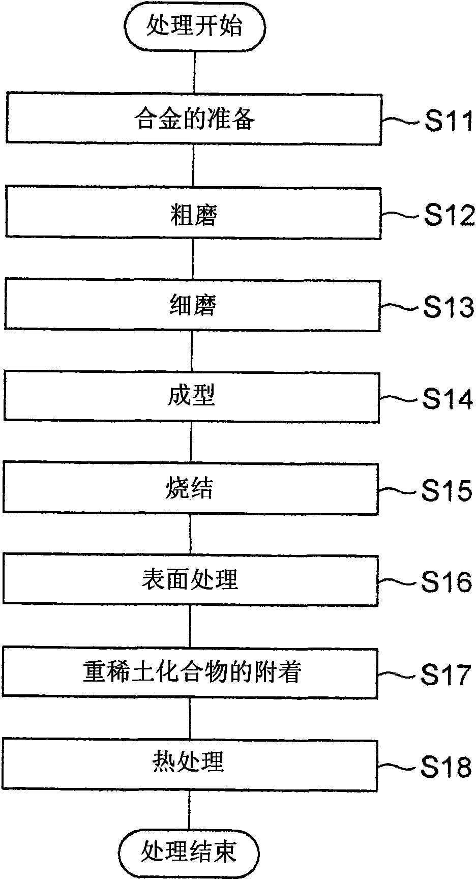
[0043] First of all, prepare the rare earth with composition 23.50wt%Nd-3.50wt%Dy-3.30wt%Pr-0.450wt%Co-0.18wt%Al-0.06wt%Cu-0.97wt%B-bal.Fe The raw material alloy of the magnet. Two types of raw material alloys were prepared: a main-phase alloy mainly forming the main phase of the magnet, and a grain boundary alloy mainly forming grain boundaries. Next, after these raw material alloys were roughly ground by hydrogen pulverization, they were 2 Air jet milling to make them into fine powder with average particle diameter D=4μm.

[0044] The obtained fine powder of the main phase alloy and the fine powder of the grain boundary alloy were mixed at a ratio of the former: the latter = 95:5 to prepare a magnetic powder as a raw material powder of a rare earth magnet. Next, using this magnetic powder, press 1.2t / cm 2 1. Under the condition of an orientation magnetic field of 15 kOe, molding in a magnetic field was performed to obtain a molded body. Then, the obtained molded body was...

Embodiment 2~6

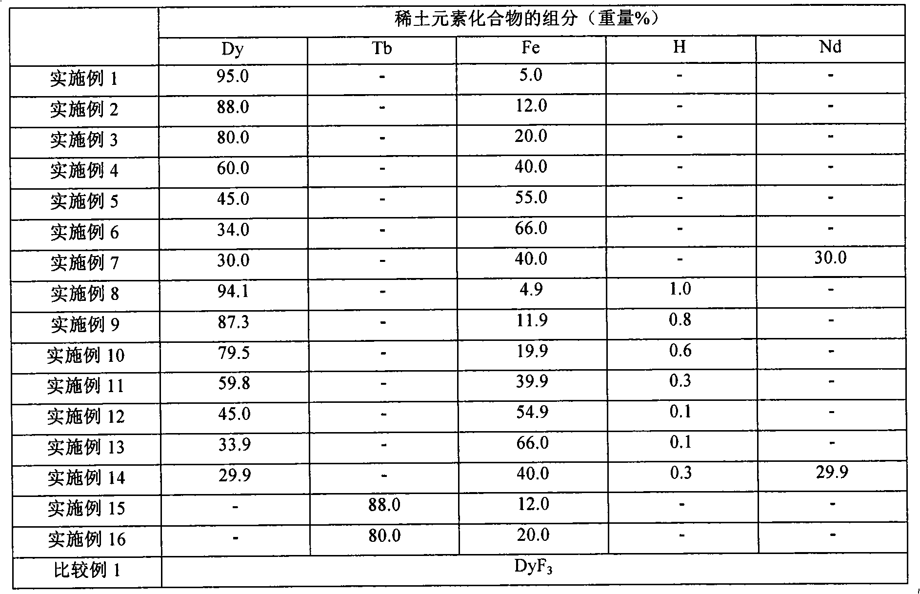
[0049] Rare earth magnets were manufactured in the same manner as in Example 1 except that the composition of DyFe was changed to those shown in Table 1.

Embodiment 7

[0051] A rare earth magnet was manufactured in the same manner as in Example 1 except that DyNdFe having the composition shown in Table 1 was used instead of DyFe.


PUM

PropertyMeasurementUnit
particle diameteraaaaaaaaaa

Abstract

The process for producing a magnet according to the invention is characterized by comprising a first step in which a heavy rare earth compound containing Dy or Th as a heavy rare earth element is adhered onto a sintered compact of a rare earth magnet and a second step in which the heavy rare earth compound-adhered sintered compact is subjected to heat treatment, wherein the heavy rare earth compound is a Dy or Th iron compound.

Description

technical field [0001] The present invention relates to a method for producing a magnet, and more specifically, to a method for producing a rare earth magnet containing a rare earth element. Background technique [0002] A rare earth magnet having an R-Fe-B (R is a rare earth element) system composition has excellent magnetic properties, and many studies have been made to further improve the magnetic properties. Generally, residual magnetic flux density (Br) and coercive force (HcJ) are used as indexes showing the magnetic properties of a magnet. Among them, HcJ has been improved by adding Dy or Tb to the rare earth magnet. [0003] However, if an element such as Dy or Tb is selected as R of the R-Fe-B-based compound, the saturation magnetization of the compound becomes small, so when the added amount is too large, Br tends to decrease. Therefore, in order to reduce this adverse situation, International Publication No. 2006 / 043348 Pamphlet discloses a method, for the sinte...

Claims


Application Information

Patent Timeline
Patent Type & Authority Applications(China)
IPC IPC(8): H01F1/053H01F1/08H01F41/02B22F3/10B22F3/00
CPCH01F41/026H01F41/0293
Inventor 马场文崇中村英树田中哲增田健
Owner TDK CORPARATION
Why Eureka
Try Eureka