Ferrite magnet
A ferrite magnet, ferrite technology, applied in the direction of magnetic objects, magnetic materials, iron compounds, etc., can solve the problems of high coercivity, high residual magnetic flux density, etc.
- Summary
- Abstract
- Description
- Claims
- Application Information
AI Technical Summary
Problems solved by technology
Method used
Image
Examples
experiment example 1
[0126] [Experimental example 1] (Manufacture of ferrite sintered magnet)
[0127] First, iron oxide (Fe 2 o 3 ), strontium carbonate (SrCO 3 ), cobalt oxide (Co 3 o 4 ) and lanthanum hydroxide (La(OH) 3 ), and these raw materials were weighed so that the composition after calcination became the following composition formula.
[0128] Composition formula:
[0129] A 1-x R x (Fe 12-y Me y ) z
[0130] In the formula, A=Sr, R=La, Me=Co. In addition, x=0.80, y=0.35, and z=1.10.
[0131] Next, the weighed raw materials were mixed with a wet mill for 1 hour and pulverized to obtain a slurry (blending step). After drying the slurry, firing was carried out in air at a rate of temperature rise and fall of 15° C. / min and held at 1310° C. for 2 hours (calcination step).
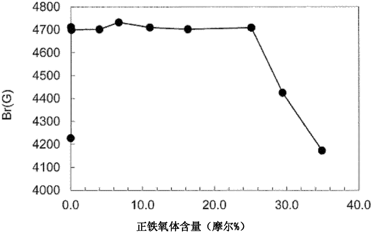
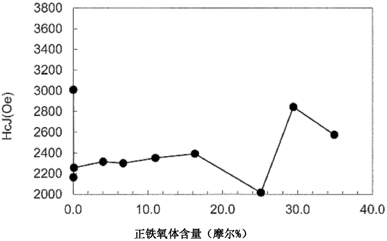
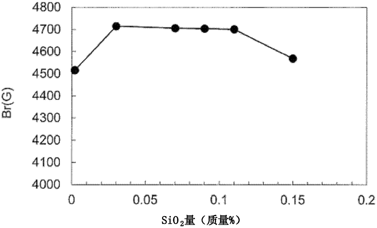
[0132] The obtained calcined powder was coarsely pulverized for 10 minutes with a small rod vibrating mill. Iron oxide, strontium carbonate, cobalt oxide, and lanthanum hydroxide were added to this coars...
experiment example 2
[0142] [Experimental example 2] (Manufacture of ferrite sintered magnet)
[0143] In Experimental Example 2, except that the composition of the sintered body after firing was the composition formula in Table 2, and the content of Si was SiO2 relative to the sintered body after firing. 2 SiO is added to the coarsely ground material in conversion to 0.05% by mass 2 , and the sintered ferrite magnet was produced in the same manner as in Experimental Example 1 except that the sintering temperature was set to 1290°C.
[0144] In this Experimental Example 2, various ferrite sintered magnets of samples 2-1 to 2-8 were manufactured so as to greatly change the atomic ratio of La (x=0.51 to 0.91) in particular. Using the ferrite sintered magnets obtained in Experimental Example 2, their ratios of Br(G), HcJ(Oe), M phase, orthoferrite phase, and hematite phase were determined in the same manner as in Experimental Example 1. The obtained results are shown in Table 2.
[0145] [Table 2]...
experiment example 3
[0148] [Experimental Example 3] (Manufacture of Ferrite Sintered Magnet)
[0149] In Experimental Example 3, except that the composition of the fired sintered body was the composition formula in Table 3, and the content of Si was SiO 2 SiO is added to the coarsely ground material in conversion to 0.05% by mass 2 Except for this, the same procedure as in Experimental Example 1 was performed to produce a sintered ferrite magnet.
[0150] In this Experimental Example 3, various ferrite sintered magnets of samples 3-1 to 3-7 were manufactured so as to significantly change the atomic ratio of Co (y=0.20 to 0.61). Using the ferrite sintered magnets obtained in Experimental Example 3, their Br(G), HcJ(Oe), M phase, orthoferrite phase, hematite phase, and spinel were obtained in the same manner as in Experimental Example 1. Ratio of stone phase. Table 3 shows the obtained results.
[0151] [table 3]
[0152]
[0153] According to Table 3, when the ratio (y) of Co is 0.30 or mo...
PUM
| Property | Measurement | Unit |
|---|---|---|
| light receiving slit | aaaaa | aaaaa |
Abstract
Description
Claims
Application Information
 - R&D
- Intellectual Property
- Life Sciences
- Materials
- Tech Scout
- Unparalleled Data Quality
- Higher Quality Content
- 60% Fewer Hallucinations
Browse by: Latest US Patents, China's latest patents, Technical Efficacy Thesaurus, Application Domain, Technology Topic, Popular Technical Reports.
© 2025 PatSnap. All rights reserved.Legal|Privacy policy|Modern Slavery Act Transparency Statement|Sitemap|About US| Contact US: help@patsnap.com


