
Driving circuit and projector

A driving circuit and circuit technology, applied in the field of projectors, can solve problems such as inability to perform precise adjustments, frequent changes in current, etc.

Inactive Publication Date: 2010-01-06
HISENSE VISUAL TECH CO LTD
View PDF1 Cites 12 Cited by
  • Summary
  • Abstract
  • Description
  • Claims
  • Application Information

AI Technical Summary

Problems solved by technology

Therefore, the current can only be limited, and precise adjustment cannot be performed. The change of the current is realized by replacing the components.
[0004] In addition, due to the adjustment of the brightness of the LED light source, the current changes more frequently, which highlights the disadvantages of the above patents.

Method used


Image

  • Driving circuit and projector
  • Driving circuit and projector

Examples


Embodiment Construction

[0022] The specific embodiments of the present invention will be described in detail below with reference to the accompanying drawings.

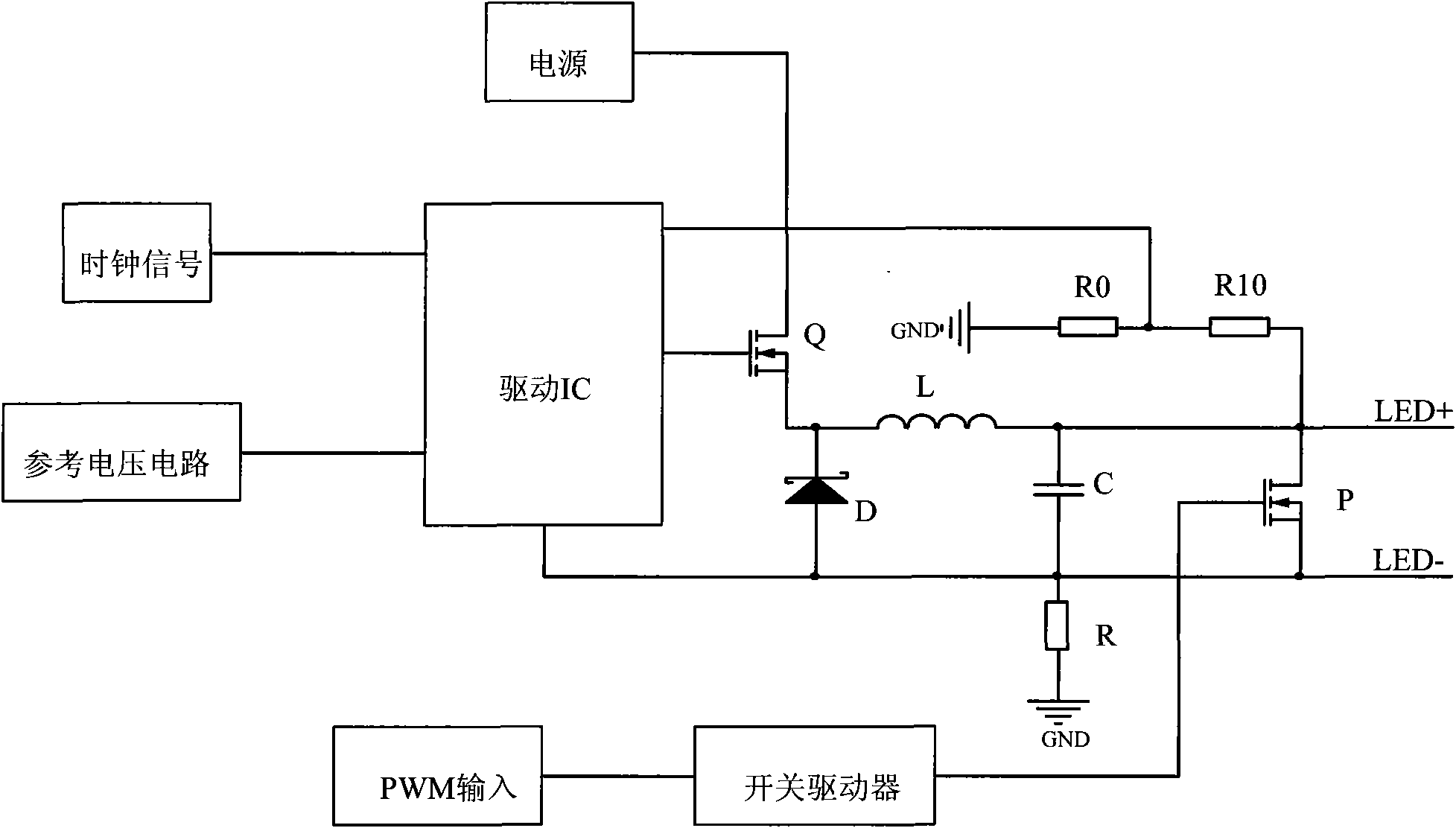
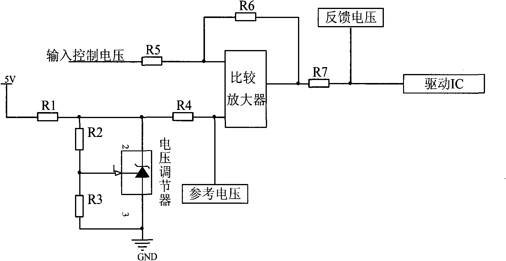
[0023] if yes figure 1 As shown, the clock signal and the reference voltage circuit are connected to the driver IC, the output of the driver IC is connected to the base of the first transistor Q, the source of the first transistor is connected to the power supply, and the drain of the first transistor is connected to the inductor L, where the The first transistor is a MOSFET, and other types of field effect transistors or triodes can also be used. The first transistor Q is connected to a step-down circuit. The step-down circuit includes an inductor L, a freewheeling diode D, a capacitor C and a sampling resistor R. One end of the inductor L is connected to the drain of the first transistor Q, and the other end of the inductor L is connected to One end of the capacitor C, the other end of the capacitor C is connected to one end of the sampli...


PUM


Abstract

The invention relates to a driving circuit which comprises a reference voltage circuit and a clock circuit, the reference voltage circuit and the clock circuit are connected onto the driving chip and comprise a first transistor and a second transistor, the output end of the driving chip is connected with the input end of the first transistor, the output end of the first transistor is connected with a voltage reduction circuit, the two ends of a capacitance of the voltage reduction circuit are connected with the two output ends of the second transistor, the other end of the capacitance is back fed to the driving chip, the two output ends of the second transistor are connected with a load, the input end of the second transistor is connected with a pulse-width circuit, the invention also relates to a projector comprising the driving circuit.

Description

technical field [0001] The invention relates to a driving circuit for driving LED lamps and adjusting the brightness, and also relates to a projector with the driving device. Background technique [0002] The light source required by projection display equipment generally requires high brightness, high luminous efficiency, high light availability, wide color gamut, long life, etc., and can have a luminous spectrum suitable for RGB display, good color rendering and color reproduction ability. . With the development of high-power, ultra-high-brightness LED, it becomes possible to become the light source of projection display equipment. LEDs are more and more commonly used light-emitting devices. More and more projection devices use high-power LEDs. For devices that require high output luminous flux, the LEDs used have the characteristics of high current and low voltage. Since LED is a constant current driving device, to ensure high output light quality and consistency of bri...

Claims


Application Information

Patent Timeline
IPC IPC(8): H05B37/00H05B37/02G03B21/14
CPCY02B20/42Y02B20/40
Inventor 郭大勃张海翔刘卫东
Owner HISENSE VISUAL TECH CO LTD
Learn More