
Process for reducing carbon dioxide emission in a power plant

A carbon dioxide and power generation device technology, applied in the direction of direct carbon dioxide emission reduction, carbon dioxide storage, chemical instruments and methods, etc., can solve the problems of increasing the total cost of the method and operational complexity

Active Publication Date: 2010-01-06
SHELL INT RES MAATSCHAPPIJ BV
View PDF2 Cites 6 Cited by
  • Summary
  • Abstract
  • Description
  • Claims
  • Application Information

AI Technical Summary

Problems solved by technology

The need for this blower increases the overall cost and operational complexity of the process

Method used


Image

  • Process for reducing carbon dioxide emission in a power plant

Examples


Embodiment Construction

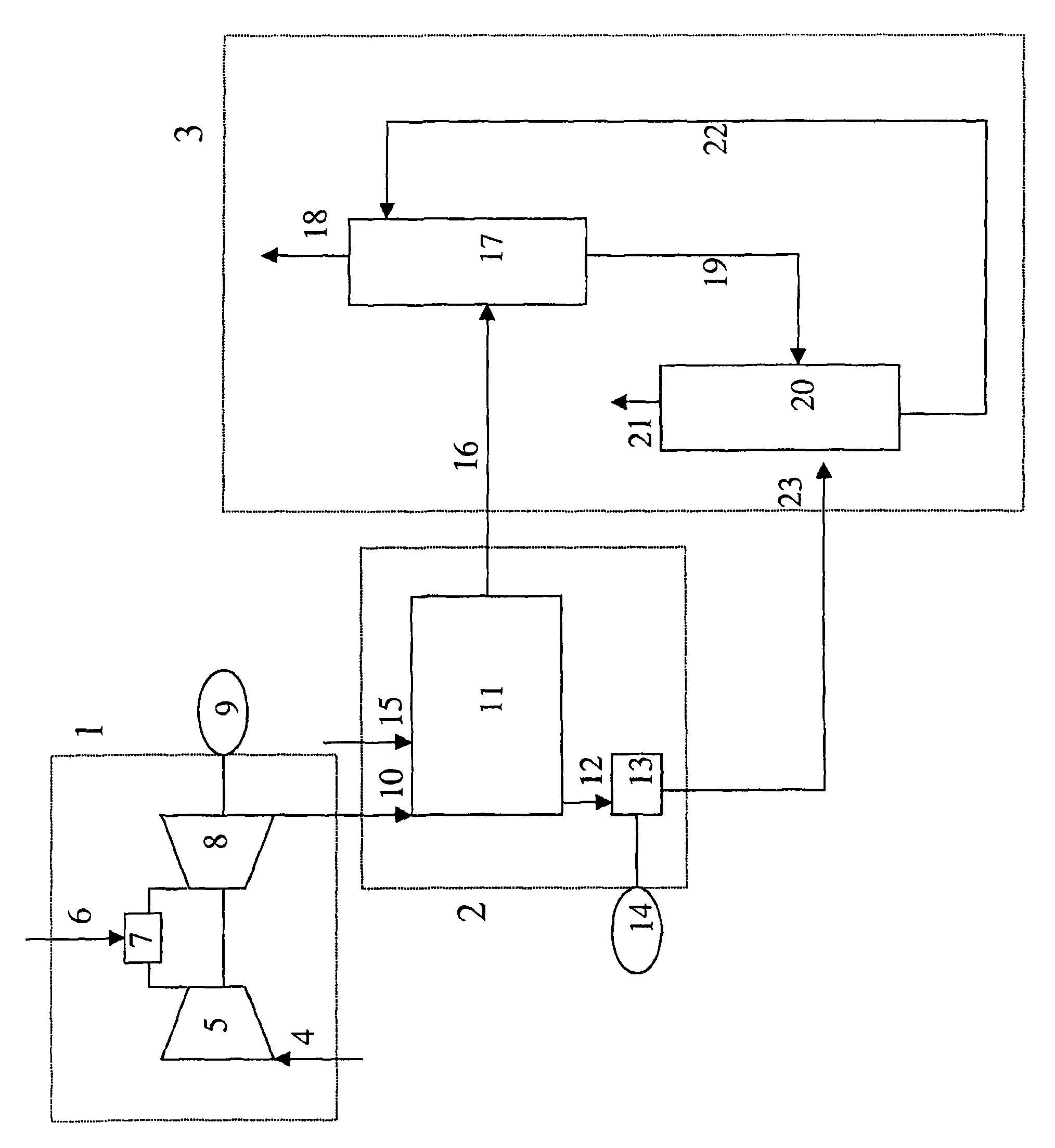
[0009] In the method, a power plant comprising at least one gas turbine is used. Typically, fuel and oxygen-containing gas are fed into the combustion zone of a gas turbine. In the combustion zone of a gas turbine, fuel is combusted to produce hot combustion gases. The hot combustion gases are expanded in a gas turbine (usually via an array of expander blades arranged in a row), and used to generate electricity by a generator. Suitable fuels for combustion in gas turbines include natural gas and syngas.

[0010] In step (a), the hot exhaust gas leaving the gas turbine is introduced into a heat recovery steam generator unit. The hot exhaust gas leaving the gas turbine has a certain high pressure. The pressure of the hot exhaust gas is determined by the setup and / or construction of the gas turbine. For example, a gas turbine typically includes a sequence of expander blades arranged in rows: by changing the number of expander blade rows, the back pressure of the gas turbine c...


PUM


Abstract

A process for reducing CO2 emission in a power plant, wherein the power plant comprises at least one gas turbine coupled to a heat recovery steam generator unit and the CO2 capture unit comprises an absorber and a regenerator, the process comprising the steps of: (a) introducing hot exhaust gas exiting a gas turbine having a certain elevated pressure into a heat recovery steam generator unit to produce steam and a flue gas stream comprising carbon dioxide; (b) removing carbon dioxide from the flue gas stream comprising carbon dioxide by contacting the flue gas stream with absorbing liquid in an absorber having an elevated operating pressure to obtain absorbing liquid enriched in carbon dioxide and a purified flue gas stream, wherein the settings and / or construction of the gas turbine are adjusted such that the hot exhaust gas exiting the gas turbine has a pressure of at least 40% of the elevated operating pressure of the absorber.

Description

technical field [0001] The present invention relates to the reduction of carbon dioxide (CO 2 ) method of emission. Background technique [0002] Most of the world's energy supply is provided by burning fuels, especially natural gas or synthesis gas, in power plants. The fuel is typically combusted in one or more gas turbines, and the resulting gas is used to generate steam. The steam is then used to generate electricity. Combustion of fuel produces CO 2 . In recent decades, CO emissions to the atmosphere 2 The volume has increased significantly on a global scale. According to the Kyoto agreement, CO must be reduced 2 emissions to prevent or offset undesired climate change. [0003] CO in gas turbine flue gas 2 Concentrations depend on the fuel and combustion and heat recovery process applied, and are generally relatively low, typically 3-15%. Therefore, reducing CO 2 emissions make it desirable to separate CO from exhaust 2 , because it is too expensive to compr...

Claims


Application Information

Patent Timeline
Patent Type & Authority Applications(China)
IPC IPC(8): B01D53/62
CPCB01D2257/504Y02C10/14Y02E20/18Y02C10/06Y02C10/04B01D53/62F05D2270/301F01K23/10F02C9/00F05B2270/301F05D2230/50F05B2230/50B01D2252/204B01D53/1425Y02A50/20Y02C20/40Y02E20/32
Inventor K-J·李G·普罗托帕帕斯
Owner SHELL INT RES MAATSCHAPPIJ BV
Learn More