Device and method for making robot track given route at high accuracy

A technology of specifying paths and robots, which is applied in the field of tracking compensation, can solve problems such as low hardware requirements, tool center point positioning accuracy that cannot meet laser welding requirements, etc., and achieve high tracking accuracy, cost reduction, and simple operation.

Inactive Publication Date: 2010-01-13
SHENYANG INST OF AUTOMATION - CHINESE ACAD OF SCI
View PDF7 Cites 102 Cited by
  • Summary
  • Abstract
  • Description
  • Claims
  • Application Information

AI Technical Summary

Problems solved by technology

[0015] The purpose of the present invention is to provide a laser processing head device for tracking a specified path with low hardware requirements, and a path tracking/compensation control m...

Method used


Image

  • Device and method for making robot track given route at high accuracy
  • Device and method for making robot track given route at high accuracy
  • Device and method for making robot track given route at high accuracy

Examples


Embodiment 1

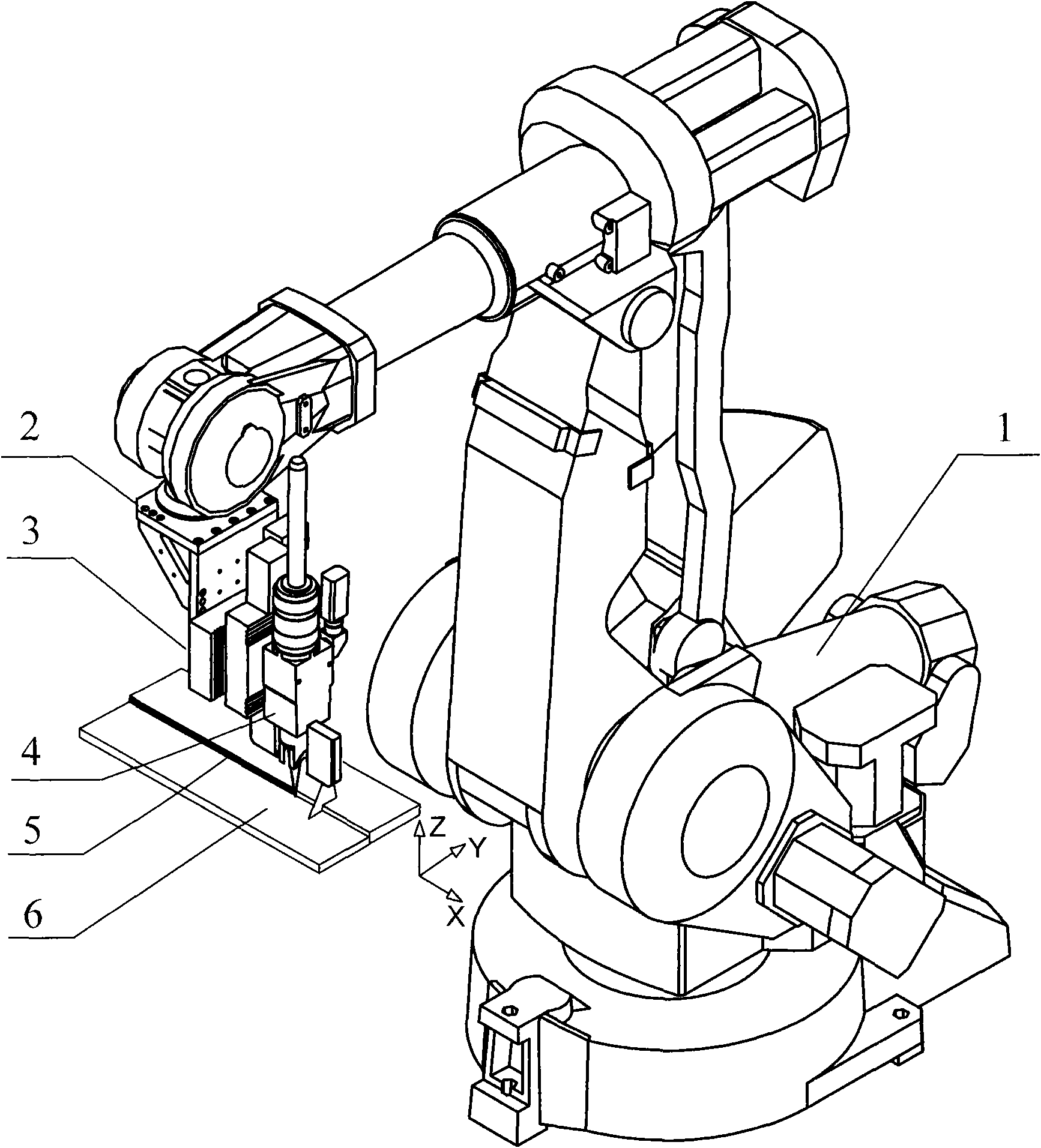
[0051] Such as figure 1 As shown, a device for enabling a robot to track a specified path with high precision is mainly composed of a robot body 1 , a tool holder 2 , a position correction device 3 and a laser processing head unit 4 . The laser processing head unit 4 is installed on the position correction device 3 , the position correction device 3 is installed on the tool support 2 , and the tool support 2 is installed at the end of the robot body 1 . The robot initially positions the laser processing head unit above the welding seam 5 of the welding material 6 .

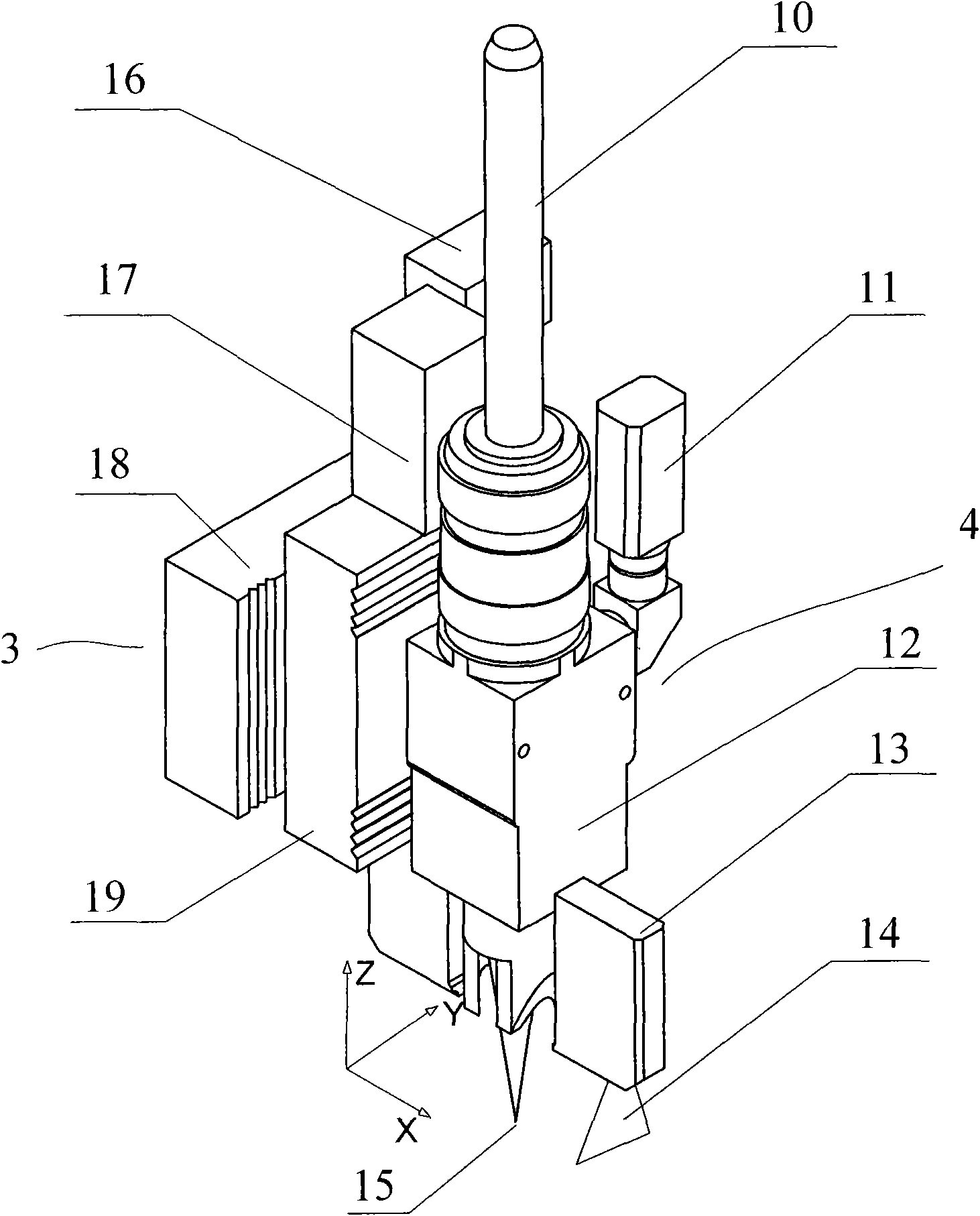
[0052] Such as figure 1 , figure 2 As shown, in order to facilitate the description of the present invention, the forward direction of the weld seam is defined as the positive direction of the X-axis, the axis of the laser processing head is the direction of the Z-axis, and the direction of the Y-axis is defined according to the right-hand rule.

[0053] Such as figure 2 As shown, the laser processing head u...


PUM


Abstract

The invention relates to a device and a method for making a robot track a given route at high accuracy, in particular to a robot processing system for performing route tracking and deviation compensation by comprehensively utilizing a coaxial vision sensing system and a welding seam position measurement sensing system, and a route tracking method, which are used for high-accuracy processing of laser welding and the like. The implementation process is divided into three stages; the first two stages comprehensively utilize welding seam position measurement information and coaxial vision measurement information to calculate the deviation between the front welding seam position and the central point of a robot tool and a welding seam so as to obtain the compensation data of the track deviation of the central point of the robot tool and the welding seam position reference data; and the stage of actual welding utilizes the welding seam position measurement information and the welding seam position reference data to perform tracking and compensation control, a position correcting device corrects the motion of a robot system so that the central point of the robot tool moves forwards continuously along the given route, and the deviation of the given route is smaller than the route repeat accuracy of the robot. The device and the method can be widely applied to various occasions required to improve the motion path accuracy of the robot.

Description

technical field [0001] The invention relates to tracking compensation technology, in particular to a device and a path tracking compensation method for enabling a robot to track a specified path (such as a welding seam) with high precision. The device and method can enable a robot system with low precision to realize high-precision processes such as laser welding. Background technique [0002] Some advanced technology applications hope to use robots with large working space and good motion flexibility, but also put forward high requirements for the positioning accuracy of robots. For example, laser welding has the following remarkable characteristics: the welding speed can reach more than 4m-15m / min, while the welding speed of traditional arc welding is generally only 0.5m-1.0m / min; the tracking positioning accuracy is high, and the welding seam tracking error requirements Within ±(0.05-0.1mm), far below the tracking error ±0.5mm required in arc welding. Existing laser wel...

Claims


Application Information

Patent Timeline
IPC IPC(8): B25J9/10B25J9/22B25J19/02
CPCG05B2219/36405G05B2219/4705G05B2219/36407B23K26/0884B25J9/1684
Inventor 罗振军王琛元贺云姜春英邹媛媛田永利
Owner SHENYANG INST OF AUTOMATION - CHINESE ACAD OF SCI
Why Eureka
Try Eureka