Apparatus for the separation of solid particles from water and haudraulic installation containing such separation apparatus

A solid particle and equipment technology, applied in the field of energy conversion equipment, can solve the problems of reduced solid particle content, ineffective sand tank tunnels, increased hydraulic equipment installation costs and operating costs, and achieve the effect of reducing workload and costs

Inactive Publication Date: 2010-01-20
ALSTOM RENEWABLE TECH
View PDF7 Cites 12 Cited by
  • Summary
  • Abstract
  • Description
  • Claims
  • Application Information

AI Technical Summary

Problems solved by technology

This resulted in extensive civil engineering work with a corresponding increase in the installation and operating costs of state of the art hydraulic equipment
Also, such sand tank tunnels are not very efficient, as the solids content is only reduced by about 50% after water flows through such a device

Method used


Image

  • Apparatus for the separation of solid particles from water and haudraulic installation containing such separation apparatus
  • Apparatus for the separation of solid particles from water and haudraulic installation containing such separation apparatus
  • Apparatus for the separation of solid particles from water and haudraulic installation containing such separation apparatus

Examples


Embodiment Construction

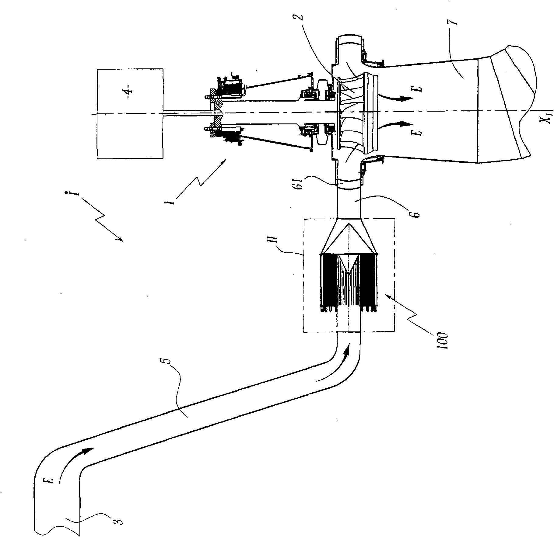
[0033] figure 1 The shown plant I comprises a Francis type turbine 1 with its impeller 2 for passing a forced flow E from a water inlet 3 set about a vertical axis X 1 Rotating, the above-mentioned water inlet 3 takes the flow from a reservoir, such as a dam, or the flow from an undammed river. The turbine 1 is coupled to an alternator 4 which delivers an alternating current to an electrical network (not shown) as the impeller 2 rotates.

[0034] The hydraulic pipe 5 that brings the water flow E into the impeller 2 extends between the water inlet 3 and a supply tank 6 equipped with guide vanes 61 for regulating the water flow E. Downstream of the device I is provided a suction line 7 for conveying the water flow E.

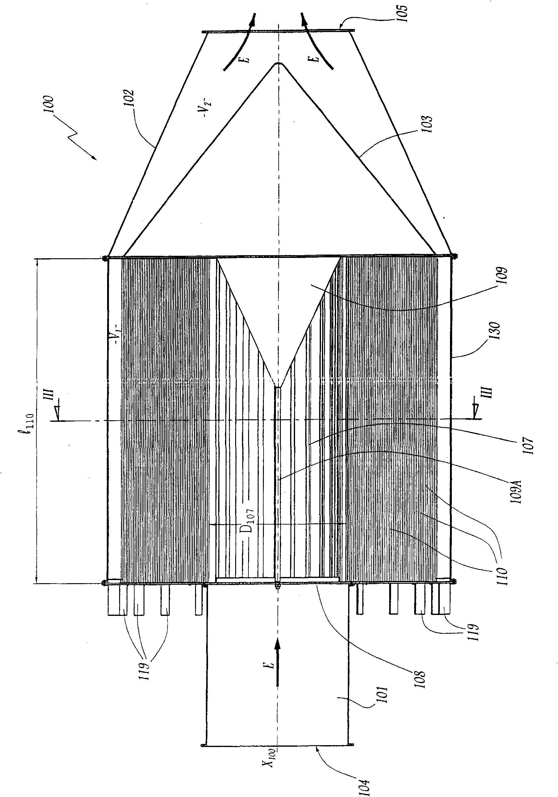
[0035] The device 100 interposed between the water inlet 3 and the supply tank 6 serves to separate the solid particles found in the water flow E from the water constituting this flow. The device 100 comprises a cylindrical inlet duct 101 having a circular cros...


PUM


Abstract

The device (100) serves to separate solid particles from the water of a flow (E) feeding a hydraulic machine of the turbine, pump, or turbine-pump type. The device has flow inlet and outlet zones (104, 105) for the flow that are spaced apart along an advance axis (X100) of flow advance-through the device (100). The device (100) comprises a plurality of ducts (110) placed in parallel, each having a mouth and a downstream end between the inlet zone (104) and the outlet zone (105). In section perpendicular to the advance axis (X100), each duct presents a section in the form of a spiral with a radius of curvature that increases from the mouth towards the downstream end or from the downstream end towards the mouth, with each duct (110) presenting a thickness measured in a generally radial direction relative to the advance axis that is less than 10% of the width (l110) of said duct, measured parallel to said axis (X100).

Description

technical field [0001] The invention relates to a device for separating solid particles from flowing water, and also to an energy conversion device comprising such a device. Background technique [0002] In the field of devices for converting hydraulic energy into electrical or mechanical energy, it is well known to send a flow of water to a hydraulic machine, such as a turbine, which interacts with the blades of the turbine. Depending on the weather conditions and the nature of the ground it passes through, the water flow may carry a greater or lesser content of solid particles such as sand which wear down the parts of the machinery it comes into contact with. [0003] A number of different devices are known for retaining or separating these solids from water streams. These include, inter alia, dams and settling basins, filter grids and sand tank tunnels. A sand tank tunnel is a conduit placed in the ground within which the flow of water delivered to the hydraulic machine...

Claims


Application Information

Patent Timeline
Patent Type & Authority Applications(China)
IPC IPC(8): B01D21/26B04C3/00E02B8/00
CPCY02E10/226F03B11/08B04C1/00B04C7/00Y02E10/20
Inventor S·普里让
Owner ALSTOM RENEWABLE TECH
Why Eureka
Try Eureka