Power balance oil extractor

A technology of power balance and pumping unit, which is applied in the direction of mechanical equipment, machine/engine, liquid variable capacity machinery, etc. It can solve the problems of high parameter adjustment and balance adjustment intensity, high energy consumption, and large fluctuations in motor output power. , to achieve the effects of stable output power and load fluctuations, increased effective load rate, and reduced one-time investment

Inactive Publication Date: 2012-01-25
CHINA UNIV OF PETROLEUM (EAST CHINA)
View PDF6 Cites 2 Cited by
  • Summary
  • Abstract
  • Description
  • Claims
  • Application Information

AI Technical Summary

Problems solved by technology

At present, the main problem in the oil production process of the beam pumping unit is the low efficiency of the system, and the average efficiency is about 23%.
The main reason is that there are many power transmission links, single function, large size and self-weight, which requires a high-power motor, high energy consumption, and low effective load rate
In addition, due to the complex and cumbersome structure, the overall size is too large, and the parameters and balance adjustment are relatively strong.
At the same time, the output power of the motor is zero at the upper and lower dead centers of the up and down strokes of the pumping unit, and the motor does not perform work. The output power of the motor and the torque of the reducer fluctuate greatly. image 3 The output power diagram of the motor when there is no counterweight is shown. At the upper and lower dead center positions of the oil pump crank, the output power of the motor is zero and fluctuates greatly; Figure 4 Shown is the output power diagram of the motor after the conventional pumping unit is equipped with a load counterweight. Although the fluctuation of the output power has been reduced, the output power of the motor is still zero at the upper and lower dead centers of the pumping crank, and the movement of the whole pumping system is stable. performance is still poor, thus affecting the service life of the motor

Method used


Image

  • Power balance oil extractor
  • Power balance oil extractor
  • Power balance oil extractor

Examples


Embodiment Construction

[0016] The present invention will be further described below in conjunction with accompanying drawing:

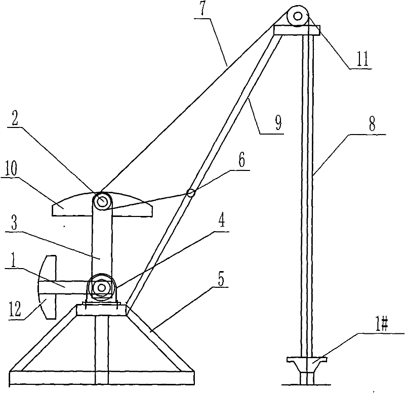
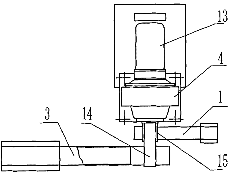
[0017] attached by figure 1 to attach Figure 5 As shown, the power balance pumping unit includes a motor 13, a speed reducer 4, a frame 5, an oil pump crank 3, a power balance weight crank 1, a load counterweight 10, a power balance counterweight 12, a flexible oil pumping rope 7 and a connecting rod. Rod 9 etc. The lower part of the frame 5 fixes the motor 13 and connects it to the reducer 4. The reducer 4 has a main output shaft 14 and an auxiliary output shaft 15. The main output shaft 14 is fixed with the oil pump crank 3, and the oil pump crank 3 is fixed with a load The counterweight 10 drives the load counterweight 10 to rotate in a circle, the power balance weight crank 1 is fixed on the auxiliary output shaft 15, the power balance counterweight 12 is fixed on the power balance weight crank 1, and the power balance counterweight 12 is driven to make a circular m...


PUM


Abstract

The invention discloses a power balance oil extractor. The power balance oil extractor mainly solves the problem that the existing oil extractor has bad movement performance, big loading fluctuation, high energy consumption and bigger adjusting parameter and adjusting balance strength. The power balance oil extractor is characterized in that a reducer drives an oil pumping crank by a main output shaft and drives a power balance heavy crank by an auxiliary output shaft; the rotating speed of the auxiliary output shaft is two times of the rotating speed of the main output shaft; the power balance heavy crank at the dead center position above the oil pumping crank lags behind 90 degrees with respect to the oil pumping crank; the power balance heavy crank at the dead center position under theoil pumping crank advances 90 degrees with respect to the oil pumping crank; a flexible oil pumping rope bypasses an oil pumping chain wheel at the upper end of a well-head bracket and a crank chain wheel on the crank in sequence, and then is fixed on a gemel seat which is fixed on a connecting rod; and both ends of the connecting rod are respectively fixed on a machine frame and the well-head bracket. The oil extractor stably operates, has simple structure, convenient parameter and balance adjustment, stable electromotor power, reducer torsion and loading fluctuation.

Description

technical field [0001] The invention relates to a lifting device used in the field of oil production in an oil field, in particular to a power-balanced pumping unit. Background technique [0002] Pumping unit oil production is the main means of oilfield production in my country, accounting for more than 90% of the pumping wells. The main problem existing in the oil recovery process of the beam pumping unit at present is that the system efficiency is low, and the average efficiency is about 23%. The main reason is that there are many power transmission links, single function, large size and self-weight, which requires a high-power motor, high energy consumption, and low effective load rate. In addition, due to the complex and cumbersome structure, the overall size is too large, and the parameter adjustment and balance adjustment are relatively intensive. At the same time, the output power of the motor is zero at the upper and lower dead centers of the up and down strokes of...

Claims


Application Information

Patent Timeline
Patent Type & Authority Patents(China)
IPC IPC(8): E21B43/00F16H37/12F04B47/14
Inventor 韩修廷李俊亮李晓东王学来孙盛祥李娟
Owner CHINA UNIV OF PETROLEUM (EAST CHINA)
Why Eureka
Try Eureka