System and method for storing crankcase gases to improve engine air-fuel control

A crankcase and engine technology, applied in the direction of engine control, combustion engine, crankcase ventilation, etc., can solve the problem that the air-fuel control of the engine cannot be improved, and achieve the effect of reducing air-fuel ratio deviation and efficient combustion

Inactive Publication Date: 2010-01-20
FORD GLOBAL TECH LLC
View PDF3 Cites 16 Cited by
  • Summary
  • Abstract
  • Description
  • Claims
  • Application Information

AI Technical Summary

Problems solved by technology

As such, the system does not appear to improve air-fuel control of the engine as gases are purged from the engine crankcase

Method used


Image

  • System and method for storing crankcase gases to improve engine air-fuel control
  • System and method for storing crankcase gases to improve engine air-fuel control
  • System and method for storing crankcase gases to improve engine air-fuel control

Examples


Embodiment Construction

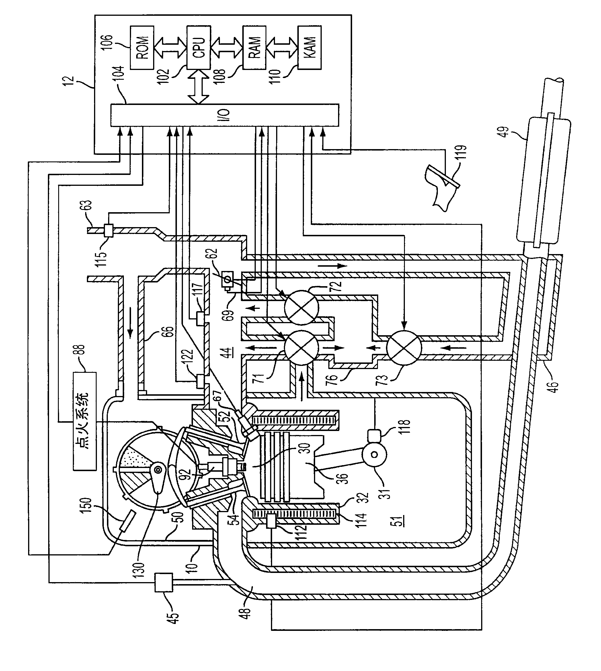
[0012] The advantages described herein will be more readily understood by reading the examples of embodiments referred to herein as the "Detailed Description" or when considered in conjunction with the accompanying drawings.

[0013] refer to figure 1 , an internal combustion engine 10 comprising a plurality of cylinders is controlled by an electronic engine controller 12, wherein figure 1 One of several cylinders is shown. Engine 10 includes combustion chamber 30 having piston 36 disposed therein and connected to crankshaft 31 and cylinder walls 32 . Combustion chamber 30 is known to communicate with intake manifold 44 and exhaust manifold 48 via respective intake valve 52 and exhaust valve 54 .

[0014] Each intake and exhaust valve is operated by a mechanical camshaft 130 that rotates by coupling the camshaft to crankshaft 31 . In alternative embodiments, one or more valves may be operated by electronic or hydraulic actuators.

[0015] Fresh air enters an intake plenum ...


PUM


Abstract

The invention relates to a system and method for storing crankcase gases to improve engine air-fuel control. The system and method for improving processing of gases contained within the crankcase of an internal combustion engine is presented. One embodiment of the present description includes a system for combusting internal combustion engine crankcase gases, the system comprising: an internal combustion engine comprising a crankcase, an intake manifold, a duct connecting the crankcase to the intake manifold, a canister comprising hydrocarbon storage media, the canister located along the length of the duct and in communication with the duct, and an adjustable valve capable of regulating flow of gases from the crankcase to the canister. This system overcomes at least some disadvantages of the above-mentioned system. The system is especially suited for single boiling point fuels because it allows the storage of such fuels until the fuel can be opportunistically combusted.

Description

technical field [0001] The present invention relates to systems and methods for combusting crankcase gases of an internal combustion engine. Background technique [0002] A system and method for operating an internal combustion engine utilizing positive crankcase ventilation (PCV) is described in US Patent 6,729,316. This patent describes a system in which emissions are drawn from the crankcase into a canister. The canister contains a decelerating and condensing element composed of glass beads. It is generally believed that the glass beads decelerate the flow from the crankcase and concentrate the hydrocarbons so that they can be released into the collector. The canister is said to separate pollutants from the crankcase and then deliver the cleaned emissions back to the engine for combustion. [0003] The system described above also has some disadvantages. In particular, fuel vapors are sent to the engine immediately after being processed through the canister. If the cr...

Claims


Application Information

Patent Timeline
Patent Type & Authority Applications(China)
IPC IPC(8): F01M13/04F02M25/06
CPCF01M13/00F01M13/0011Y02T10/121F02M25/06F01M2013/0038F02D2250/08Y02T10/12
Inventor 唐纳德·J·刘易斯杰弗里·斯科特·赫伯恩
Owner FORD GLOBAL TECH LLC
Why Eureka
Try Eureka