
System and method for driving display panel

A display panel and drive system technology, applied in the direction of static indicators, instruments, etc., can solve the problems of inconvenience, general products and methods without suitable structures and methods, etc.

Active Publication Date: 2010-01-20
HIMAX DISPLAY INC
View PDF0 Cites 6 Cited by
  • Summary
  • Abstract
  • Description
  • Claims
  • Application Information

AI Technical Summary

Problems solved by technology

[0004] It can be seen that the above-mentioned existing display panel drive system and method obviously still have inconvenience and defects in terms of product structure, manufacturing method and use, and need to be further improved urgently.
In order to solve the above-mentioned problems, the relevant manufacturers have tried their best to find a solution, but no suitable design has been developed for a long time, and there is no suitable structure and method for general products and methods to solve the above-mentioned problems. This is obviously a problem that relevant industry players are eager to solve

Method used


Image

  • System and method for driving display panel
  • System and method for driving display panel
  • System and method for driving display panel

Examples


Embodiment Construction

[0094] In order to further explain the technical means and effects of the present invention to achieve the intended purpose of the invention, the specific implementation, structure and method of the display panel drive system and method proposed according to the present invention will be described below in conjunction with the accompanying drawings and preferred embodiments. , steps, features and effects thereof are described in detail below.

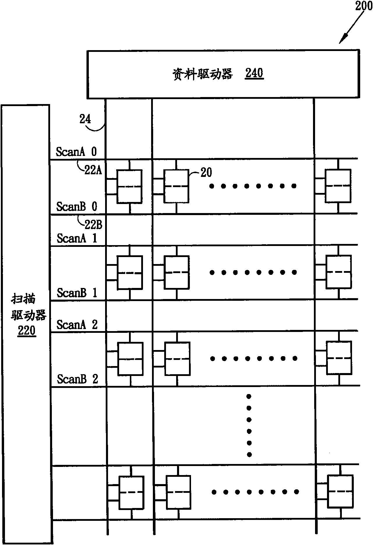
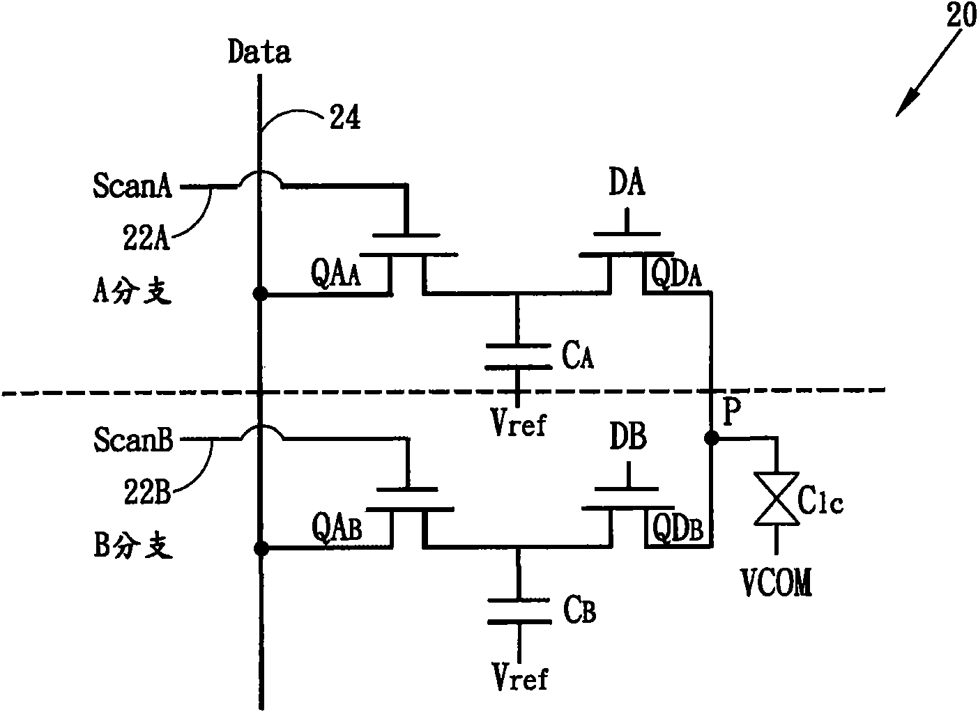
[0095] Figure 2Ais a schematic diagram showing a multi-branch (multi-branch) pixel structure 200 of a liquid crystal on silicon (LCoS) panel, Figure 2B is displayed Figure 2A A schematic diagram of a pixel unit 20 of the multi-branch pixel structure. Although liquid crystal on silicon (LCoS) is used for illustration here, those skilled in the art can apply the described structure to other reflective / transmissive display panels, such as liquid crystal displays (LCDs). exist Figure 2A Among them, a multi-branch pixel structure 200...


PUM


Abstract

The invention relates to a system and a method for driving a display panel. The display panel (such as a liquid crystal on a silicon (LCoS) panel) is in a multi-branch pixel structure. Each pixel unit of the display panel comprises at least two branches. The display panel comprises a group of sub-data lines corresponding to each row of pixel units, and the sub-data lines are respectively coupled to the two branches. According to an embodiment, the two branches are in an access mode and a display mode in order, thereby increasing the operating speed and reducing the coupling effect. According to another embodiment, a multiplexer multiplexes the two sub-data lines positioned between adjacent pixel units, and the multiplexing output is coupled to a shared data line which is shared by adjacent pixel units, thereby reducing the pixel interval.

Description

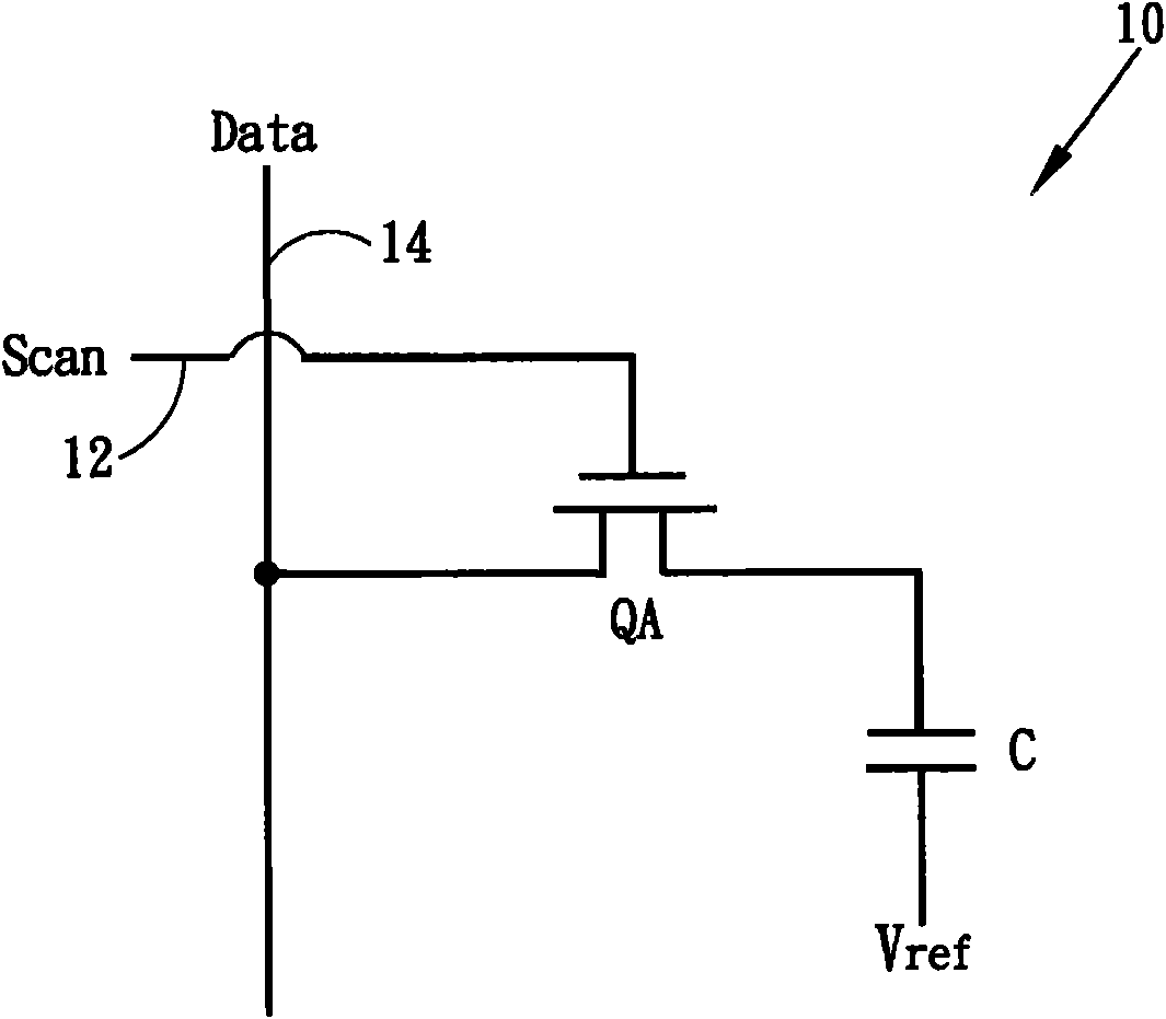
technical field [0001] The present invention relates to a display panel, in particular to a driving system and method for a liquid crystal on silicon (LCoS) panel with a multi-branch pixel structure. Background technique [0002] Liquid crystal on silicon (LCoS or LCOS) is a reflective technology. Because it can produce images with higher resolution than liquid crystal display (LCD) at a lower cost, it is commonly used as a micro-projector (micro-projector) ) or the optical engine of the micro-display system. The structure of liquid crystal on silicon (LCoS) is similar to that of liquid crystal display, usually comprising a plurality of pixels arranged in a matrix of rows and columns. figure 1 It is a schematic diagram showing a conventional liquid crystal on silicon (LCoS) pixel unit 10 , which includes a transistor QA, which is addressed by a scan signal Scan on a scan line (or gate line) 12 . The pixel unit 10 further includes a storage capacitor C, which receives and s...

Claims


Application Information

Patent Timeline
IPC IPC(8): G09G3/36
Inventor 颜呈机
Owner HIMAX DISPLAY INC
Learn More