Electromagnet device

An electromagnet and excitation technology, applied in the field of polarized electromagnet devices, can solve the problems of large power consumption and small space for winding coil 2, and achieve the effects of low power consumption, low operating voltage and low power consumption

Active Publication Date: 2010-01-20
ORMON CORP
View PDF4 Cites 29 Cited by
  • Summary
  • Abstract
  • Description
  • Claims
  • Application Information

AI Technical Summary

Problems solved by technology

Therefore, during operation, it is necessary to resist the magnetic force of the permanent magnet 5 and utilize the magnetic force of the coil 2 to drive the movable contact 6, so that the power consumption is relatively large.
[0005] In addition, in the release type electromagnetic device, the space for winding the coil 2 is very small, and if the coil 2 is used to obtain a large magnetic force, there is a problem of increasing the size of the device.

Method used


Image

  • Electromagnet device
  • Electromagnet device
  • Electromagnet device

Examples


Embodiment Construction

[0050] Refer to the attached Figure 1 to Figure 14 Embodiments of the present invention will be described.

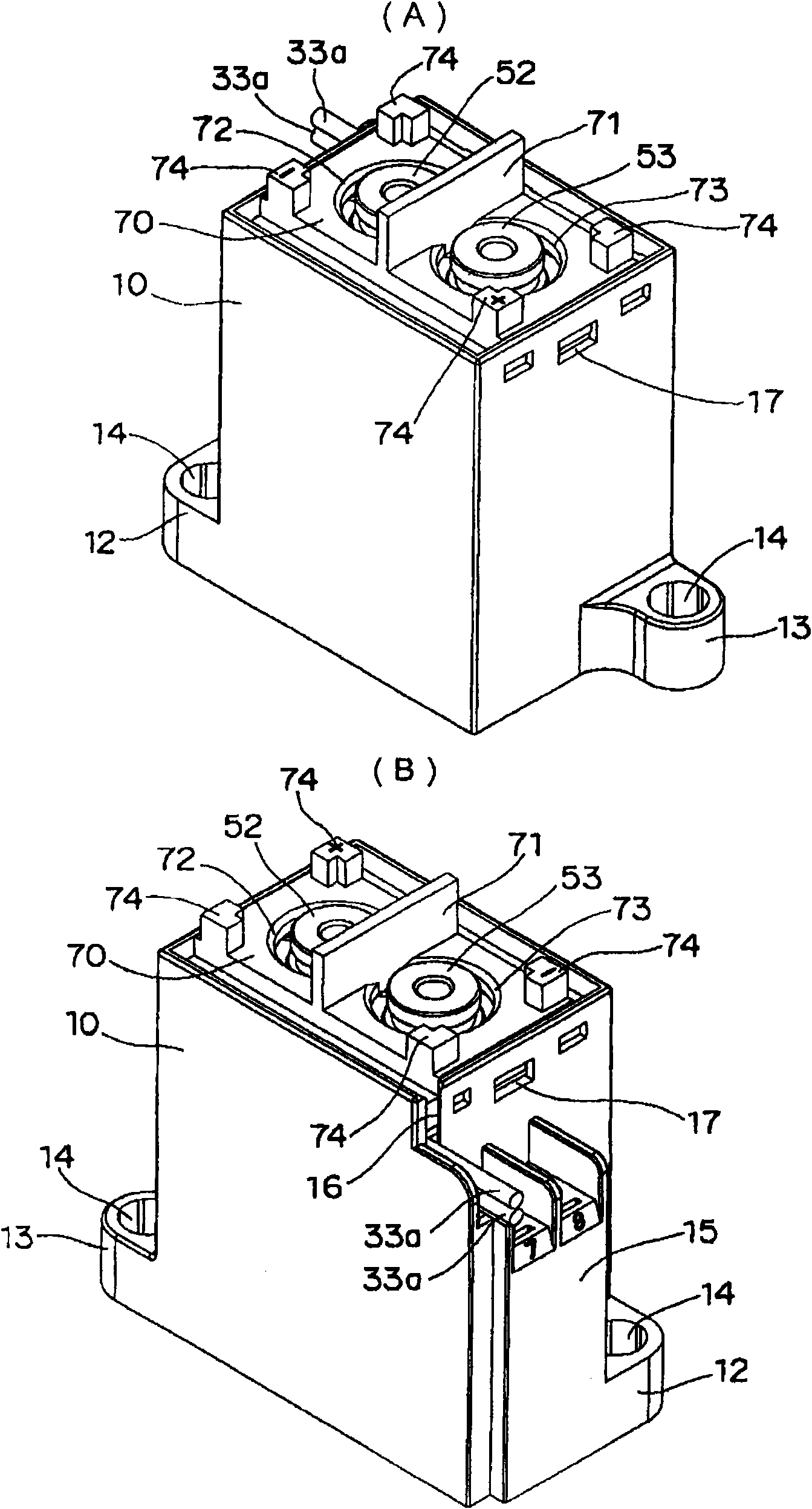
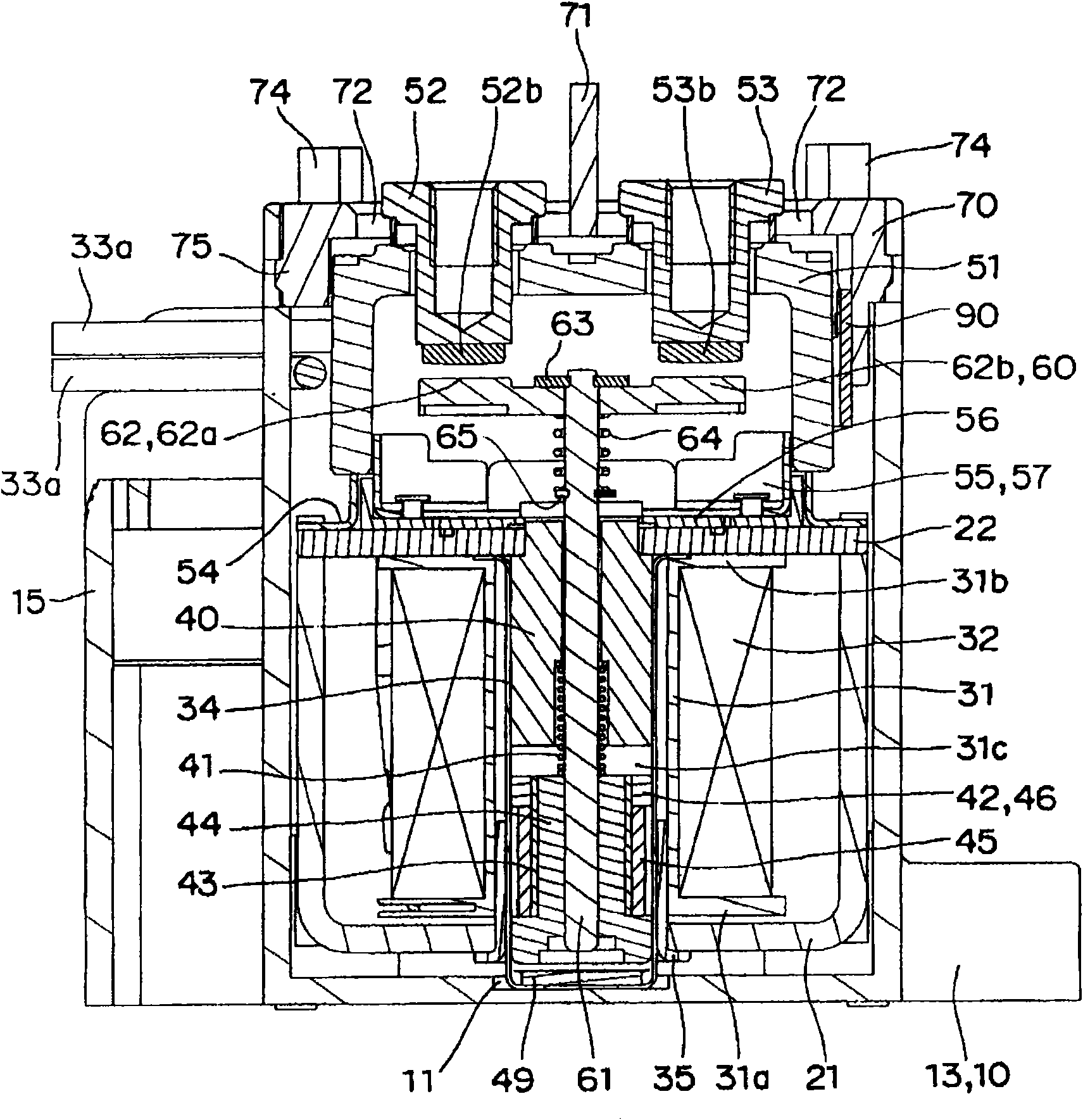
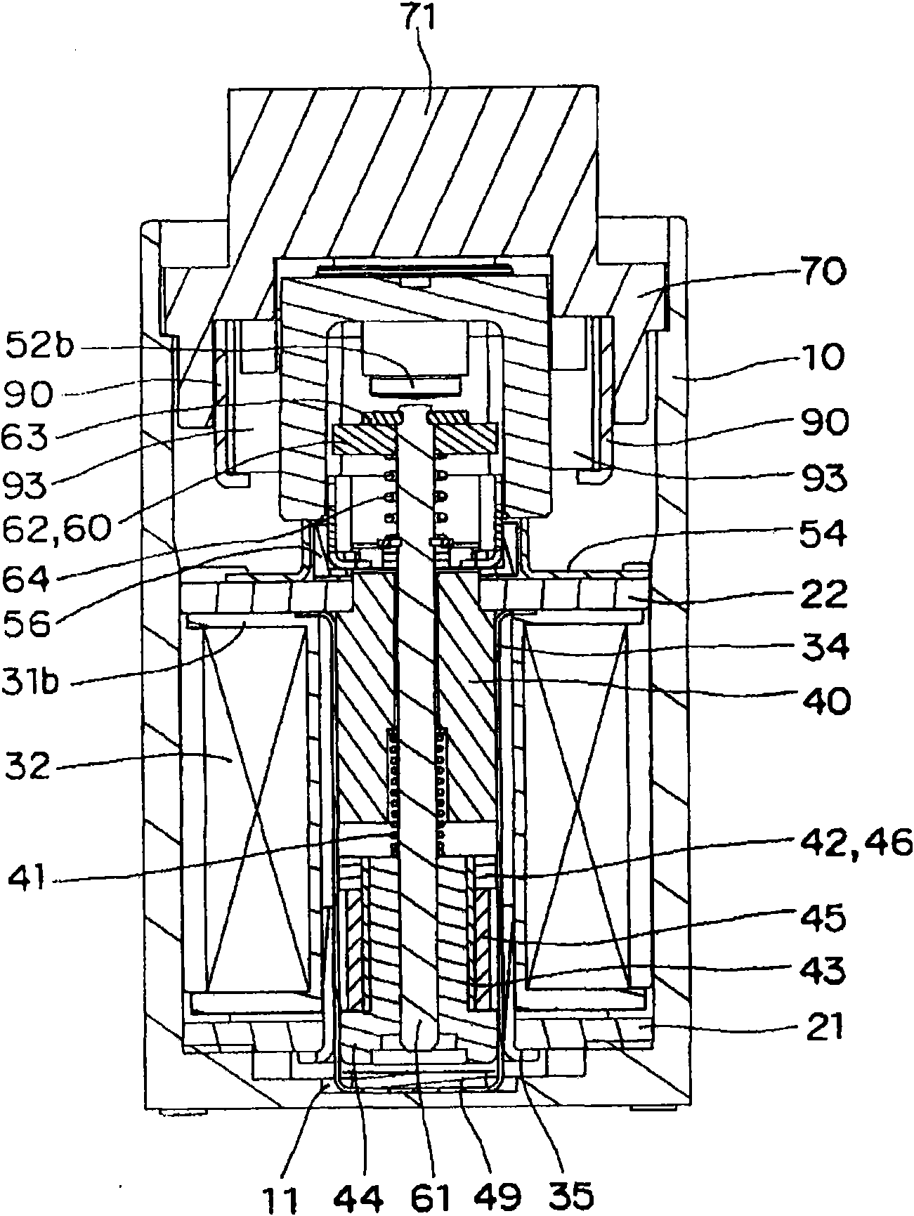
[0051] Such as Figure 1 to Figure 11 As shown, the electromagnetic relay for power load to which the polarized electromagnet device according to the first embodiment of the present invention is applied is roughly constituted as follows: a drive mechanism assembly 20 and a contact mechanism assembly 50 integrated up and down are accommodated in the casing 10, And the cover 70 is fitted and covered on the casing 10 .

[0052] Such as Figure 4 As shown, the housing 10 is in the shape of a box capable of accommodating the drive mechanism assembly 20 and the contact structure assembly 50 described later, and a fitting recess 11 for positioning the drive mechanism assembly 20 is provided at the center of the bottom surface thereof. ( figure 2 and image 3 ). In addition, the housing 10 is provided with pedestals 12 and 13 protruding laterally from the lower edge of ...


PUM


Abstract

This invention provides a small polar electromagnet device of small power consumption. Provided is a polar electromagnet device in which a drive shaft (61) is supported so as to reciprocate in an axis center direction at a center hole (31c) of a spool (31) wound with a coil (32), a movable iron core (42) is attached to a lower end of the drive shaft (61) on the same axis center, and the drive shaft (61) is reciprocated with the movable iron core (42) which reciprocates based on excitation and demagnetization of the coil. A permanent magnet (45) is integrally arranged at the movable iron core (42) on the same axis center.

Description

technical field [0001] The present invention relates to an electromagnet device, in particular to a polarized electromagnet device provided with permanent magnets. Background technique [0002] Conventionally, as a polarized electromagnet device, there is a release type electromagnetic device characterized by comprising: a movable armature held freely projecting in a predetermined direction, a fixed armature disposed opposite to the movable armature, and a protruding armature. A release spring (引外しばね) that biases the movable armature in a direction, a permanent magnet that keeps the release spring in a charged state, and a magnetic flux passing through the movable armature from the permanent magnet and the The yoke of the magnetic circuit of the fixed armature, the electromagnet that forms a diamagnetic field opposite to the magnetic field generated by the permanent magnet according to the detection result of the abnormal current, and the engaging surface when the movable ar...

Claims


Application Information

Patent Timeline
Patent Type & Authority Applications(China)
IPC IPC(8): H01F7/06H01F7/122
CPCH01F2007/083H01H51/2209H01H9/443H01H50/546H01H2051/2218H01H50/20H01F7/1615H01H2050/025
Inventor 川口健介广木和亲
Owner ORMON CORP
Why Eureka
Try Eureka