Decohering and shimming device

A guiding device and laser beam technology, applied in the laser field, can solve the problems of many system components, high installation accuracy requirements, low laser utilization rate, etc., and achieve the effect of small occupied volume and high laser utilization rate

Inactive Publication Date: 2010-01-27
PHOEBUS VISION OPTO ELECTRONICS TECH +1
View PDF4 Cites 15 Cited by
  • Summary
  • Abstract
  • Description
  • Claims
  • Application Information

AI Technical Summary

Problems solved by technology

[0003] The patents with publication numbers CN1900813 and CN1734308 and authorization number CN2555523 all use rotating diffuse transmission elements to modulate the laser light, disrupt its phase to achieve decoherence, and then couple the transmitted light into the focusing rod for shimming. This method The decoherence and shimming functions are completed by different devices, and the utilization rate of the laser light is low due to the limited transmittance of the diffuse transmission element; in addition, this method requires high installation accuracy of the components (when rotating, the incident light must always be perpendicular to the surface of the diffuse transmission element); in addition, this method causes a coupling device between the decoherence and shimming devices, making the system more components and difficult to reduce the volume

Method used


Image

  • Decohering and shimming device
  • Decohering and shimming device
  • Decohering and shimming device

Examples


Embodiment 1

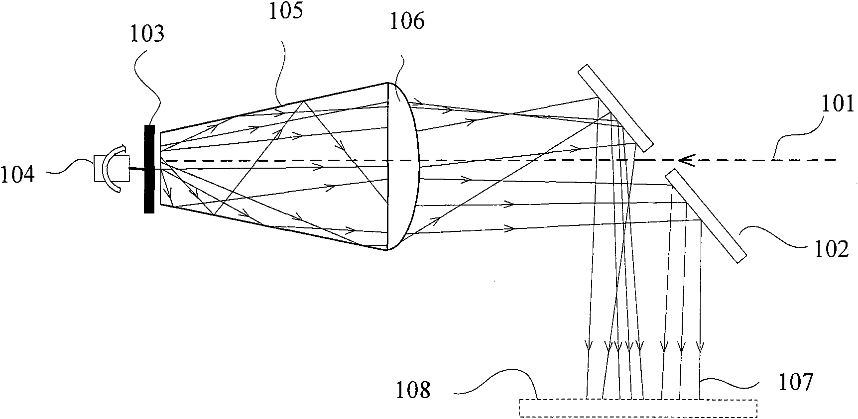
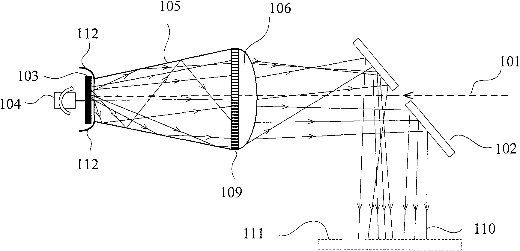
[0034] Figure 1A It is a schematic diagram of an embodiment of the present invention. The device in this embodiment includes a perforated reflector 102 , a diffuse reflector 103 , a motor 104 that rotates the diffuse reflector 103 , a total reflection cavity 105 and a free-form surface lens 106 .

[0035] The structure of the device of the present invention in this embodiment will be described in detail below. In this embodiment, a perforated reflector 102 (the perforated reflector of this structure is disclosed in the utility model patent of application number CN200720305226.8) is used to guide the coherent incident laser beam 101 into the total reflection cavity 105, in order to To minimize the impact of the apertured reflector 102 on the optical path, the size of the aperture on the apertured reflector 102 should be as small as possible, and may only be slightly larger than the beam diameter of the beam 101 . In this embodiment, the total reflection cavity 105 adopts a hol...

Embodiment 2

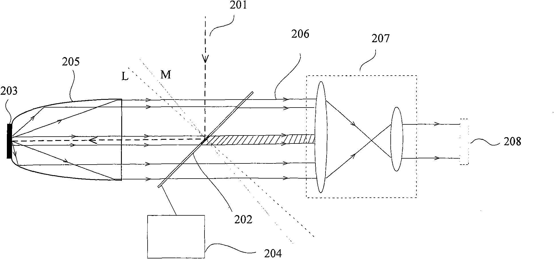
[0041] figure 2 It is a schematic diagram of another embodiment of the present invention. In this embodiment, a partial reflector 202 is used to guide the coherent incident laser beam 201 into the total reflection cavity 205. The reflective part of the partial reflector 202 is coated with a high-reflection film for the wavelength of the beam 201, and the transmissive part of the partial reflector 202 is coated with For the anti-reflection coating of the wavelength of the light beam 201, the partial reflection mirror 202 of this new structure is used because its size can completely accept all the light beams in the optical path, so that the fixing device of the partial reflection mirror 202 does not need to appear in the optical path. There is no interference in the light path. The normal of the beam 201 on the partial reflector 202 is the L axis, the M axis passes through the incident point of the beam 201 on the partial reflector 202 and slightly deviates from the L axis by...

Embodiment 3

[0047] image 3 for will Figure 1A The setup shown in is a schematic diagram of a monolithic DLP projection system. In this embodiment, the three-primary-color laser light source is composed of a red laser 301 , a green laser 302 and a blue laser 303 , and emits coherent red light 321 , green light 322 and blue light 323 respectively. The red light 321 , green light 322 , and blue light 323 time-divisionally multiplexed through the holes of the perforated mirror 305 , and are incident on the diffuse reflection plate 306 through the free-form surface lens 309 , and the diffuse reflection plate 306 is rotated by the motor 307 . The inner wall of the total reflection cavity 308 is coated with a thin film for total reflection of the red light 321, the green light 322, and the blue light 323, and the three primary color lasers are respectively processed by the diffuse reflection plate 306, the total reflection cavity 308 and the free-form surface lens 309 to form incoherent light ...


PUM


Abstract

The invention provides a decohering and shimming device, which comprises a diffuse-reflection plate, a total-reflection cavity and a homogenization lens. The decohering and shimming device utilizes a light beam guiding device to guide a light beam to be processed to the diffuse-reflection plate, and the light beam to be processed forms a plurality of beams of scattered light after the diffuse reflection of the diffuse-reflection plate; the plurality of beams of scattered light are totally reflected once or for several times on the sidewall of the total-reflection cavity along respective different propagation paths in the total-reflection cavity; optical path difference between every two beams is randomly modulated and is incoherent so that the light beams emergent from emergent ports of the total-reflection cavity are incoherent light; and then the incoherent light forms the light beams with uniformly distributed illumination in a target area through the homogenization lens. In addition, the decohering and shimming device also can adopt a mechanical means to change an incident point of the light beam to be processed on the diffuse-reflection plate all the time so as to improve the decohering effect.

Description

technical field [0001] The invention relates to the laser field, in particular to a decoherence and field shimming device in the laser display field. Background technique [0002] Due to its high brightness, monochromaticity and directivity, laser has incomparable advantages in the field of display. The basic principle of laser display is: R, G, and B three-color lasers undergo steps such as shaping, beam expansion, shimming, and decoherence respectively, and then modulated by a light valve to combine colors by a color combination prism. projection or rear projection to the screen. Different from the incoherent light sources used in other display technologies, the laser is coherent. If it is directly projected as a light source without decoherence processing, we will see obvious speckle images with uneven brightness on the receiving screen, which is the so-called Speckle, such an image quality greatly affects the viewer's experience, so in laser display technology, decoher...

Claims


Application Information

Patent Timeline
Patent Type & Authority Applications(China)
IPC IPC(8): G02B27/09G02B5/02G02B1/10G02B6/00
Inventor 成华毕勇颜世鹏张瑛贾中达
Owner PHOEBUS VISION OPTO ELECTRONICS TECH
Why Eureka
Try Eureka