LCD projection optical engine adopting LED light source and projection device thereof

A technology of projection optics and LCD screen, applied in the field of projection light source, can solve the problem of low engine efficiency

Inactive Publication Date: 2010-01-27
成都欧恒光电科技有限公司
View PDF0 Cites 13 Cited by
  • Summary
  • Abstract
  • Description
  • Claims
  • Application Information

AI Technical Summary

Problems solved by technology

The area of ​​the LCD used by a video projector may reach dozens of times that of the MD, and the beam expansion of the display device has relatively little constraints on the light source, but its popular projection lighting system with a reflective bowl and a lens makes the engine efficiency so low that it is difficult to exceed 1%

Method used


Image

  • LCD projection optical engine adopting LED light source and projection device thereof
  • LCD projection optical engine adopting LED light source and projection device thereof
  • LCD projection optical engine adopting LED light source and projection device thereof

Examples


specific Embodiment

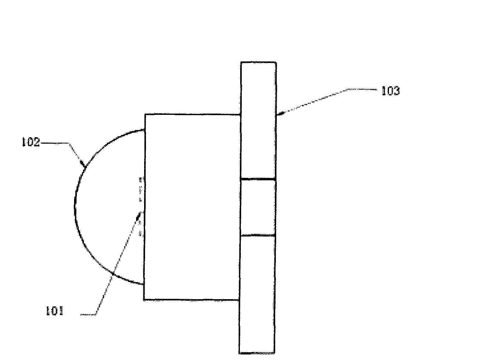
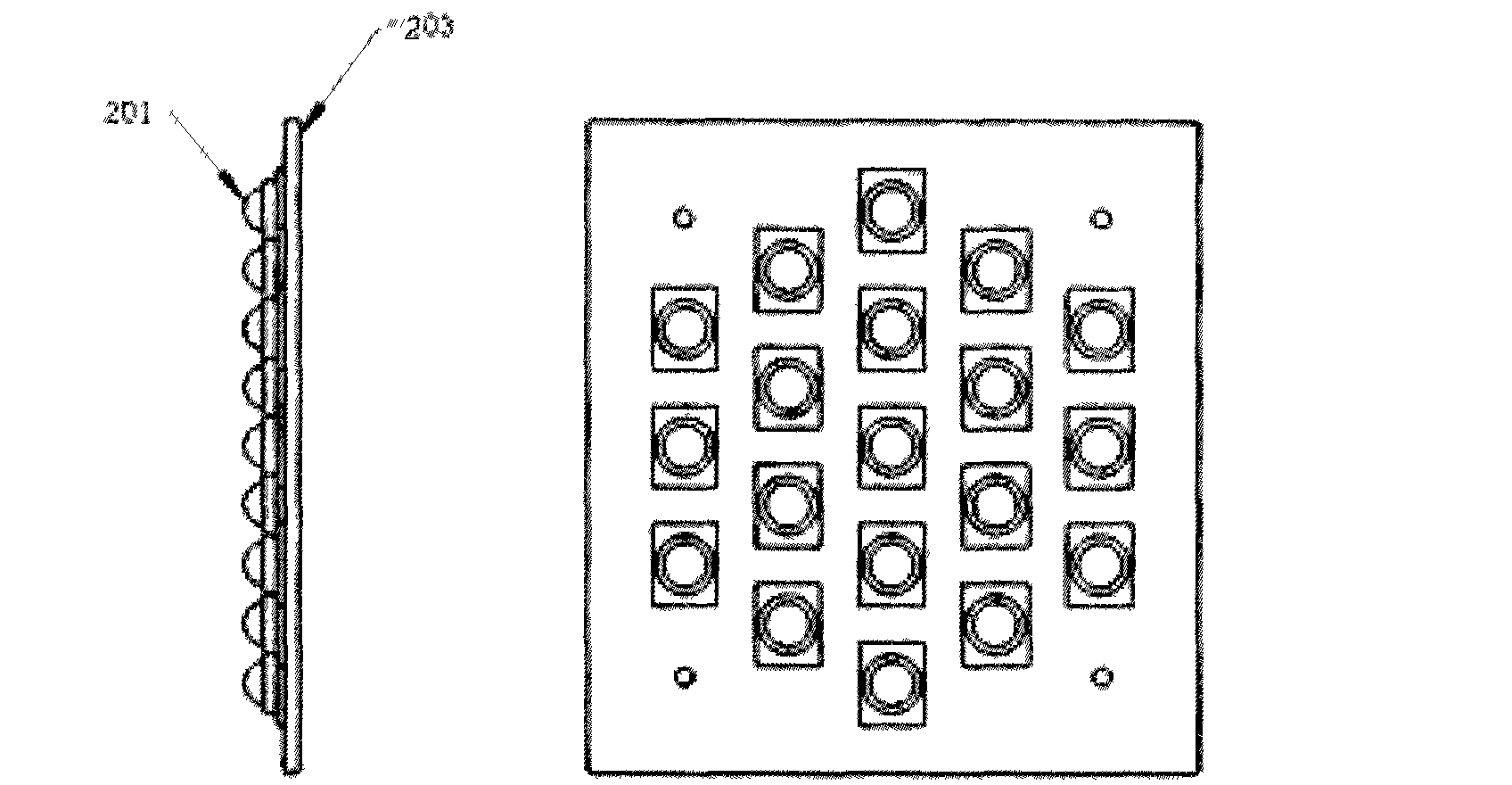
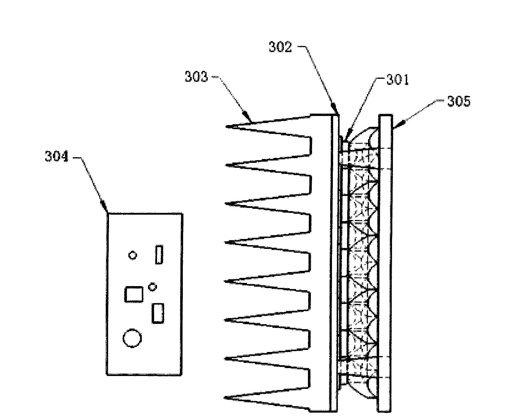
[0018] in the attached figure 1 Among them, 101 is white light power LED chips forming an array, 102 is an LED package, and 103 is a metal-based printed circuit board on which the LED array is installed. in the attached figure 2 Among them, 201 is the packaged white light power LED device forming the array, and 203 is the metal-based printed circuit board on which the LED array is installed. in the attached image 3 In the projection light source, 301 is an LED array, 302 is a metal base printed circuit board on which the LED array is installed, 303 is a radiator, 304 is a driving circuit board of the LED array, and 305 is a collector array installed on the LED array. The collectors correspond to the packaged LEDs, and the collector array corresponds to the array of packaged LEDs one by one. The driving circuit board obtains electric power from the power supply of the projection device, and drives the LED in a constant current mode. The LED converts electric energy into li...


PUM


Abstract

The invention belongs to a projection light source, a projection optical system and projection display equipment. An optical engine consists of the projection light source, a fly eye lens array, a polarized light converter, a field lens, an alignment lens, a micro lens array, an imaging device LCD screen and a projection lens. A luminous device of the projection light source is a white light power LED array, and a light concentrating element is a collector array. The luminous device, the light concentrating element, the fly eye lens array, the polarized light converter, the micro lens array and an LCD screen lamp with a CF film are reasonably designed and combined to make the projection optical engine acquire high lighting effect and high light output. Because of adopting an LED as a light source lamp, the projection optical engine also has the advantages of long service life, short response time, easy driving, no radiant heat, environmental protection, energy saving, low cost and the like. The optical engine is used as a core component, and is combined with a circuit and a complete machine structure to form a front projection and rear projection device such as a front projector or a rear projection television.

Description

technical field [0001] The invention patent belongs to projection light source, projection optical system and projection display equipment. The patent particularly relates to a single-chip LCD projection optical engine using a power white LED array to form a projection light source, a collector array and a fly-eye lens array to form a projection lighting system, a CF (color filter) film color method, and the use of this optical Engine projection device. Background technique [0002] The front projection device called Data (Data) projector adopts UHP (Ultra High Pressure Mercury Lamp) projection light source, dichroic mirror or color wheel color method, and uses high-resolution, micro-sized micro-display (MD) as an imaging device. A similar optical engine architecture is also used in MD rear projection TVs. The global annual production and sales of MD front projectors and MD rear projection TVs reach more than 7 million units. In addition, there is also a type of front pro...

Claims


Application Information

Patent Timeline
Patent Type & Authority Applications(China)
IPC IPC(8): G02B27/18G03B21/20G03B21/00
Inventor 范朝勋霍永峰
Owner 成都欧恒光电科技有限公司
Why Eureka
Try Eureka