Heat sink

A heat dissipation device and heat sink technology, applied in cooling/ventilation/heating renovation, sustainable building, energy-saving ICT, etc., can solve the problems of heating up the surrounding environment, waste of recyclable energy and energy, endangering the environment, etc., and achieve the goal of improving heat dissipation efficiency Effect

Inactive Publication Date: 2010-01-27
FU ZHUN PRECISION IND SHENZHEN +1
View PDF0 Cites 16 Cited by
  • Summary
  • Abstract
  • Description
  • Claims
  • Application Information

AI Technical Summary

Problems solved by technology

However, the existing heat dissipation devices basically exhaust the heat out of the system blindly. The exhausted heat will not only heat

Method used


Image

  • Heat sink
  • Heat sink
  • Heat sink

Examples


Embodiment Construction

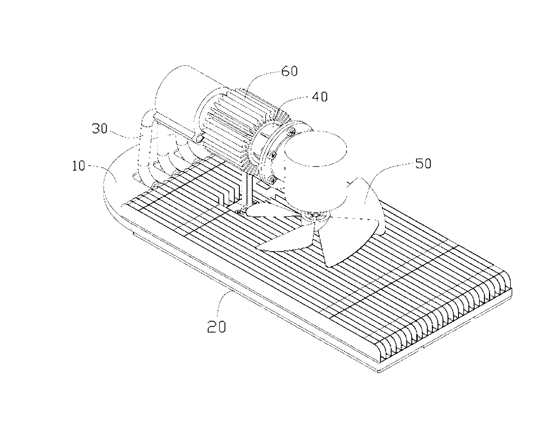
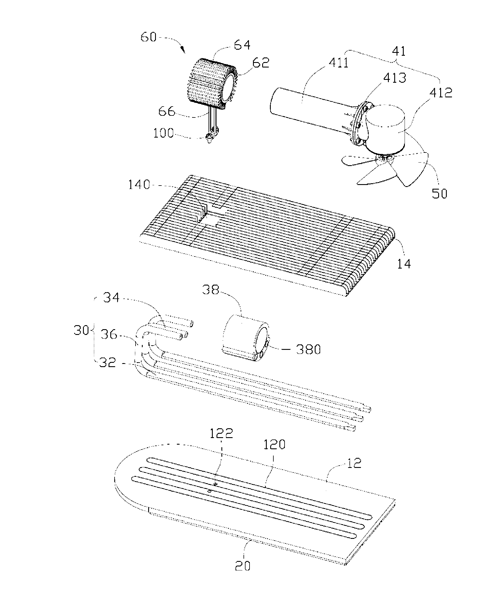
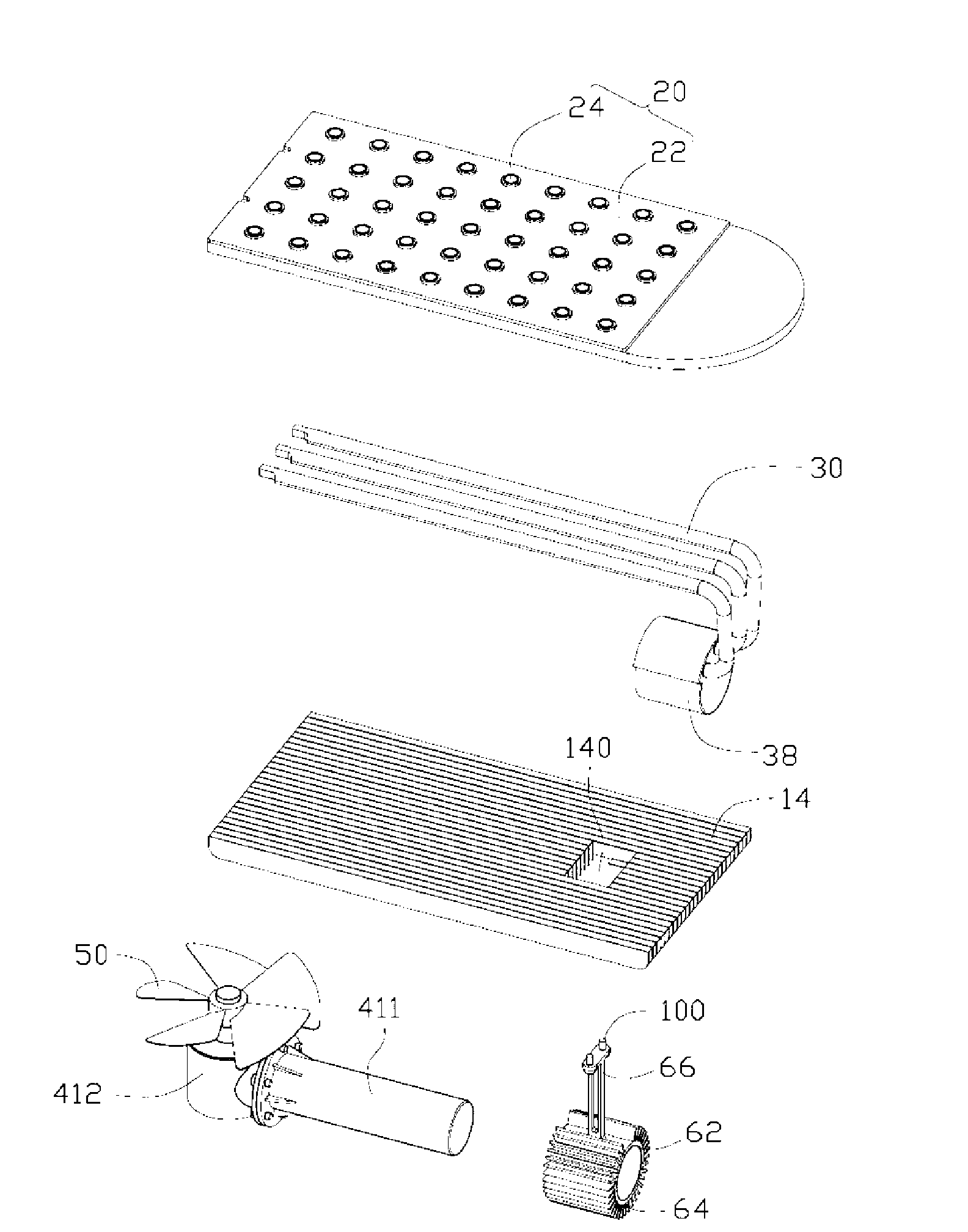
[0012] see Figure 1 to Figure 2 , the heat dissipation device of the present invention includes a first radiator 10, a power conversion device 40 arranged on the first radiator 10, a fan installed at one end of the power conversion device 40 and facing the first radiator 10 50 and a plurality of heat pipes 30 connecting the first radiator 10 and the other end of the power conversion device 40 through heat conduction. The heat dissipation device further includes a second radiator 60 sleeved on the power conversion device 40 and supported and fixed on the first radiator 10 . A heating element such as LED module 20 is pasted on the bottom surface of the first heat sink 10 .

[0013] Please also refer to image 3 , the above-mentioned first heat sink 10 is made of a metal with good thermal conductivity, such as copper, aluminum and the like. The first heat sink 10 is in the shape of a cuboid and includes a rectangular substrate 12 and a plurality of first heat dissipation fins...


PUM


Abstract

A heat sink comprises a first radiator, a power conversion device arranged above the first radiator, a fan installed at the other end of the power conversion device and a plurality of heat pipes connected with the first radiator and one end of the power conversion device in a heat-conducting manner, wherein, the power conversion device comprises a hollow shell, a power piston and a gastight piston, which are arranged in the shell, crank linkages respectively connected with the power piston and the gastight piston and a crankshaft flywheel in drive connection with the crank linkages; the power piston and the gastight piston reciprocate in the shell and drive the fan connected with the crankshaft flywheel to be rotated by the crank linkages. Compared with the prior art, the heat sink of the invention adopts the heat generated when the heating elements work to be converted into mechanical energy which is used for driving the fan to be rotated by the power conversion device, thereby effectively utilizing energy cycle for auxiliary heat dissipation, further increasing the heat dissipation efficiency and needing no power supply equipment to provide power.

Description

technical field [0001] The invention relates to a heat dissipation device, in particular to a heat dissipation device for dissipating heat from a light-emitting diode module. Background technique [0002] Electronic components will generate a lot of heat when they are working. If the heat is not dissipated in time, it will affect the working life of electronic components and even lead to damage of electronic components. [0003] At present, a heat sink is usually installed on the electronic components to dissipate heat. A common heat dissipation device includes a base plate in contact with a heating electronic component and a plurality of heat dissipation fins arranged at intervals on the base plate. However, the existing heat dissipation devices basically exhaust the heat out of the system blindly. The exhausted heat will not only heat up the surrounding environment and endanger the environment, but also cause waste of energy due to unreasonable use of recyclable energy. ...

Claims


Application Information

Patent Timeline
IPC IPC(8): H05K7/20H01L23/34H01L23/433H01L23/467
CPCY02B60/1275Y02D10/00
Inventor 周志勇丁巧利曹海兵
Owner FU ZHUN PRECISION IND SHENZHEN
Why Eureka
Try Eureka