
Method for processing impact cylinder of pneumatic tool

A technology of pneumatic tools and processing methods, which is applied in the direction of manufacturing tools, furnaces, heat treatment equipment, etc., and can solve problems such as part fracture, shape and position tolerance, deformation, etc.

Inactive Publication Date: 2010-02-03
ZHEJIANG FENGLI INTELLIGENT TECH CO LTD
View PDF0 Cites 2 Cited by
  • Summary
  • Abstract
  • Description
  • Claims
  • Application Information

AI Technical Summary

Problems solved by technology

The processing flow of prior art to impact cylinder is: forging---normalizing heat treatment---rough machining---wire cutting (semicircle hole A and round hole)---quenching heat treatment---finishing, because wire cutting operation is placed on Before the heat treatment process, although the hardness of the inner wall of the installation hole of the impact block can be guaranteed, due to the deformation after heat treatment, the shape and position tolerance of the hole is seriously out of tolerance, resulting in poor working condition of the impactor and early fracture of the parts, resulting in certain economic losses. loss

Method used


Image

  • Method for processing impact cylinder of pneumatic tool
  • Method for processing impact cylinder of pneumatic tool
  • Method for processing impact cylinder of pneumatic tool

Examples


Embodiment Construction

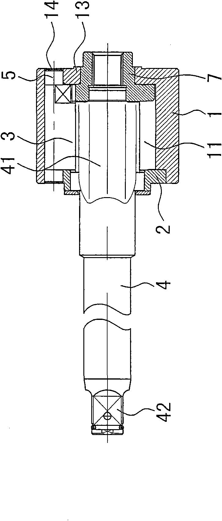
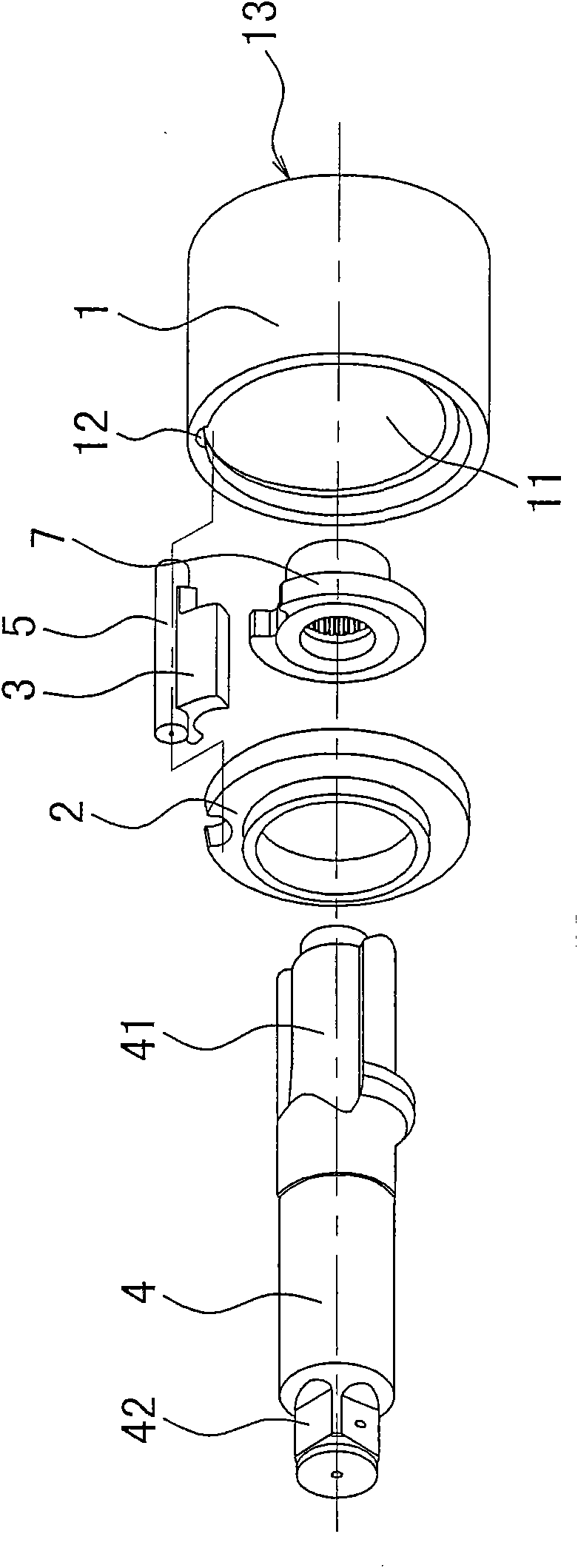
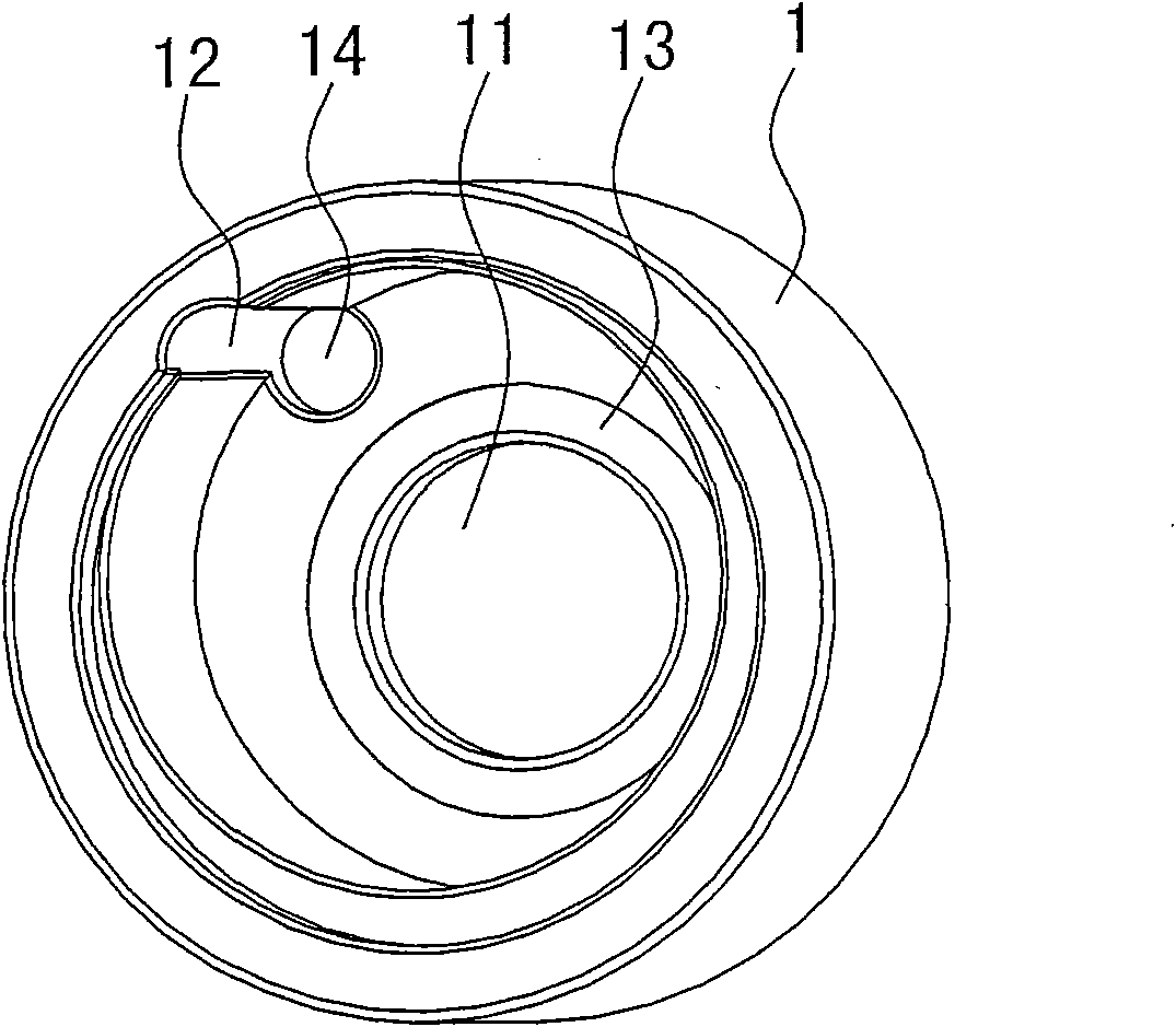
[0018] The invention discloses a processing method of an impact cylinder of an air tool. The air tool is composed of a power source and an impact mechanism. The power source is provided by an air motor. The air motor is composed of blades, rotors and cylinders, such as figure 1 , figure 2 As shown, the impact mechanism includes a striking shaft 4, and one end of the striking shaft is formed with a striking surface 41, the striking surface 41 is matched with the striking block 3, and the striking block 3 is provided with a striking pin 5, and the two ends of the striking pin are respectively passed through the inner lining 2 and the striking block 3. The transmission sleeve 7 is fixed in the impact cylinder 1, the transmission sleeve 7 is engaged with the rotor, the other end of the impact shaft 4 is made into a square head 42, and the square head is connected to the sleeve. It is characterized in that the processing steps of the impact cylinder are:

[0019] a. Take the metal...


PUM


Abstract

The invention relates to a method for processing an impact cylinder of a pneumatic tool. The pneumatic tool consists of a power source and an impact mechanism, wherein the power source is supplied by an air motor which consists of blades, a rotor and a cylinder; the impact mechanism comprises a striking shaft; one end of the striking shaft is provided with a striking surface which is matched witha striking block; the striking block is provided with a striking pin; two ends of the striking pin are fixed in the impact cylinder through a liner and a drive sleeve respectively; the drive sleeve is meshed with the rotor; and the other end of the striking shaft is made into a rectangular head which is connected with a sleeve. The method is characterized by comprising the following steps for processing the impact cylinder: taking metal blanks, and forging the metal blanks into a solid cylinder; performing normalizing heat treatment on the forged and molded solid cylinder; forming a center hole in the center of the solid cylinder through rough machining, and reserving an end face as an end cover; performing quenching heat treatment; performing fine machining; processing a semicircle orifice straight-through end cover at one end of the inner wall of the cylinder center hole through linear cutting, and forming a round orifice on the end cover; performing destressing tempering; and performing sandblasting on the surface of the cylinder and the hole wall to obtain the finished product.

Description

technical field [0001] The invention relates to a processing method of an impact cylinder of a pneumatic tool, which belongs to the field of mechanical manufacturing. Background technique [0002] Pneumatic tools refer to tools that use compressed air as a power source, such as pneumatic grinders, pneumatic polishers, air drills, pneumatic wrenches, pneumatic screwdrivers, jackhammers, etc., and are mainly used for assembling and disassembling various machinery and equipment. Pneumatic tools are composed of a power source and an impact mechanism. The power source is provided by an air motor. The air motor is composed of blades, rotors and cylinders. Most of the impact mechanisms are pinless and single pendulum. Shaft, one end of the striking shaft is made with a striking surface, the striking surface is matched with the striking block, and the striking block is provided with a striking pin, and the two ends of the striking pin are respectively fixed in the impact cylinder th...

Claims


Application Information

Patent Timeline
Patent Type & Authority Applications(China)
IPC IPC(8): B23P15/00C21D9/00
Inventor 王友利
Owner ZHEJIANG FENGLI INTELLIGENT TECH CO LTD
Learn More