Suspension type construction method of top pipe shaft

A construction method and a suspended technology, applied in the field of suspended construction of pipe jacking shafts, can solve problems such as large excavation area, long construction period, and threats to building safety, so as to reduce the impact on the environment, shorten the construction period, and save support cost effect

Inactive Publication Date: 2010-02-03
ZHENGZHOU MUNICIPAL ENG CORP +1
View PDF0 Cites 12 Cited by
  • Summary
  • Abstract
  • Description
  • Claims
  • Application Information

AI Technical Summary

Problems solved by technology

Shafts (working shafts, receiving shafts, etc.) must be made during pipe jacking construction. Existing shafts must be constructed by excavating foundation pits or using caisson construction techniques after measuring and setting out lines and determining the position of the shaft. Some shaft construction methods have the following defects: 1. When the shaft is close to the building, if there is no protective structure, it will pose a threat to the safety of the nearby buildings (it is easy to cause the nearby building foundation to sink). , it is necessary to increase the cost of expensive protective structures, and the protective structures cannot be taken out and reused after the construction is completed, reducing costs and ensuring building safety cannot be achieved at the same time
2. When the shaft is located on the road, the construction method of excavating the foundation pit requires a large area for construction, and the road needs to be closed for construction, and all vehicles must detour
3. The shaft produced by the existing shaft construction method has the defect of easy lateral deformation
4. The excavation area is large and the construction period is long
5. In the existing shaft construction method, after the foundation pit is excavated, the shaft wall is poured from bottom to top, and there is no construction method of reverse pouring the shaft wall from top to bottom

Method used


Image

  • Suspension type construction method of top pipe shaft
  • Suspension type construction method of top pipe shaft
  • Suspension type construction method of top pipe shaft

Examples


Embodiment Construction

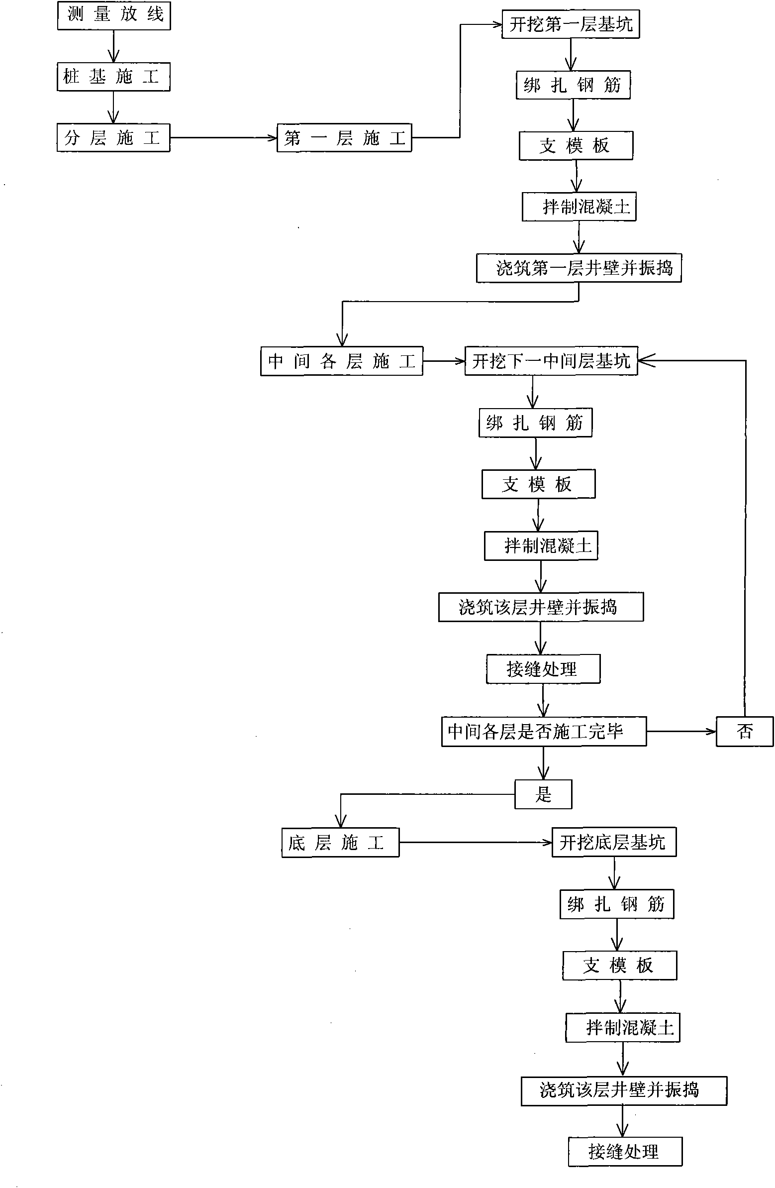
[0022] like figure 1 Shown, pipe jacking shaft suspension type construction method of the present invention comprises following construction steps:

[0023] The first is the shaft position measurement and setting out.

[0024] The second is pile foundation construction, at least four engineering piles are vertically pressed into the ground, and the engineering piles are evenly arranged along the periphery of the shaft, and the offset of the engineering piles during construction should be less than the thickness of the well wall. The engineering piles are reinforced concrete cast-in-situ piles or steel pipe piles, and the diameter of the engineering piles is not more than one-third of the wall thickness of the shaft.

[0025] The third is layered construction, that is, layered excavation of the foundation pit and layered pouring of the shaft wall, wherein the size and position of the foundation pit are the same as the vertical shaft, and this step includes three sub-steps in t...


PUM


Abstract

The invention discloses a suspension type construction method of a top pipe shaft. The suspension type construction method is characterized by comprising the following construction steps: firstly, measuring and laying at the position of the shaft; secondly, pipe foundation construction: pressing at least four engineering piles into the ground and distributing the engineering piles along the periphery of the shaft; and thirdly, layered construction, namely excavating a foundation pit in a layering manner and casting the shaft wall in a layering manner, wherein the size and the position of the foundation pit are the same as the shaft; and the third step comprises three substeps in sequence: the first substep is the construction of a first layer, namely the uppermost layer, excavating the first layer and carrying out casting to the shaft wall of the uppermost layer; the second substep is the construction of all the layers in the middle, downward continuously excavating in a layer manner and carrying out casting to the shaft wall layer by layer; and the third substep is construction of the bottom layer, excavating the bottommost layer and casting the shaft wall and the shaft bottom ofthe layer. The suspension type construction method creates the construction method of inversely casting the shaft wall from top to bottom, shortens the construction period, does not need to arrange asupporting structure additionally in construction, solves the problem of lateral deformation of the original maintaining wall and improves the earthquake resistance of the shaft.

Description

technical field [0001] The invention relates to a construction method for a pipe jacking shaft, in particular to a suspended construction method for a pipe jacking shaft. Background technique [0002] Pipe jacking construction is the main construction method of trenchless underground pipeline construction in urban drainage projects. It does not need to excavate the surface layer, and it can cross roads, railways, rivers, ground buildings, underground structures and various underground pipelines. It has the advantages of no pollution to the environment, no impact on traffic, little damage to the stratum structure, safe and reliable construction, short cycle, no need to transport and pile up miscellaneous soil, low cost, and significant social and economic benefits. Shafts (working shafts, receiving shafts, etc.) must be made during pipe jacking construction. Existing shafts must be constructed by excavating foundation pits or using caisson construction techniques after measur...

Claims


Application Information

Patent Timeline
Patent Type & Authority Applications(China)
IPC IPC(8): E02D29/00E02D29/12
Inventor 吴纪东罗付军多化勇吴湘云杨艳
Owner ZHENGZHOU MUNICIPAL ENG CORP
Why Eureka
Try Eureka