Waste-heat boiler

A waste heat boiler and superheater technology, applied in the boiler field, can solve the problems of low-temperature corrosion of metal, difficult cleaning of metal surface, and influence on the operation of boiler equipment, etc., and achieve the effect of avoiding low-temperature corrosion

Active Publication Date: 2010-02-03
SUZHOU HAILU HEAVY IND
View PDF5 Cites 12 Cited by
  • Summary
  • Abstract
  • Description
  • Claims
  • Application Information

AI Technical Summary

Problems solved by technology

Because the flue gas contains a lot of water, there are some acidic substances such as sulfur dioxide and hydrocyanic acid, it is easy to cause low-temperature corrosion to metals at low temperature (flue gas dew point temperature), and at the same time, the flue gas contains a large amount of fine powder dust , due to static electricity, it is very easy to adhere to the metal surface and is not easy to clean, affecting the operation of the boiler and even the entire set of equipment

Method used


Image

  • Waste-heat boiler

Examples


Embodiment Construction

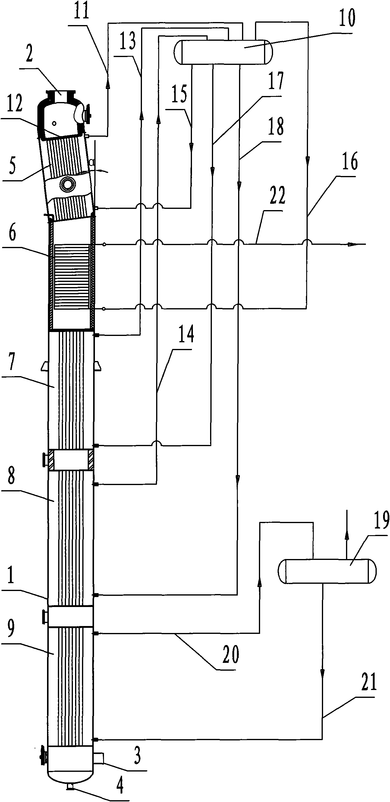
[0011] The structure and working principle of the waste heat boiler of the present invention will be further described in detail below in conjunction with the accompanying drawings.

[0012] Such as figure 1 As shown, a waste heat boiler includes a vertical cylindrical shell 1, a flue gas inlet 2 is provided at the upper end of the shell 1, a flue gas outlet 3 and an ash outlet 4 are provided at the lower end, and the inside of the shell 1 rises from above. The first intermediate pressure evaporator 5, the superheater 6, the second intermediate pressure evaporator 7, the third intermediate pressure evaporator 8 and the low pressure evaporator 9 are arranged in sequence below, and the first intermediate pressure evaporator 5, the second intermediate pressure The evaporator 7, the third intermediate pressure evaporator 8 and the low pressure evaporator 9 are all fire tube type (the flue gas flowing in the heat exchange tube is a fire tube type, and the flue gas flowing outside the ...


PUM


Abstract

The invention discloses a waste-heat boiler for a low pressure gasification device, comprising a vertical cylinder-type shell. A flue gas inlet is arranged at the upper end of the shell, a flue gas outlet and an ash outlet are arranged at the lower end, and a first middle pressure evaporator, a super-heater, a second middle pressure evaporator and a low pressure evaporator are sequentially arranged under the flue gas inlet arranged in the shell, wherein the first middle pressure evaporator, the second middle pressure evaporator and the low pressure evaporator are all fire pipe types, a lead-out pipe and a descending pipe are respectively arranged at two ends of the first middle pressure evaporator, the second middle pressure evaporator and the low pressure evaporator, the descending pipe and the lead-out pipe on the first middle pressure evaporator and the second middle pressure evaporator are respectively connected with a middle pressure steam pocket, the descending pipe and the lead-out pipe on the low pressure evaporator are connected with a low pressure steam pocket, a superheat evaporation pipe at one end of the super-heater is connected with the middle pressure steam pocket,and the other end is connected with a steam output pipe, therefore, the invention is suitable for heat energy recycle of the flue gas.

Description

Technical field [0001] The invention relates to the field of boilers, in particular to a waste heat boiler for recovering waste heat from a low-pressure coal gasification device in the coal chemical industry. Background technique [0002] The waste heat boiler is a device that uses the heat energy in the high-temperature flue gas produced by the previous device to convert it into the heat energy of the medium (water or steam) to be utilized. [0003] In the coal gasification process of the low pressure process (the working pressure of the coal gasifier is less than or equal to 1.0Mpa, the low pressure process gasification is compared with the Shell coal gasification process gasifier pressure of more than 3.0Mpa), the flue gas temperature from the coal gasifier reaches 950℃~1050℃, this part of the flue gas contains a lot of heat energy, and the waste heat boiler must be used to recover the heat. Due to the large amount of moisture in the flue gas, there are also some acidic substan...

Claims


Application Information

Patent Timeline
IPC IPC(8): F22B1/18
Inventor 钱飞舟俞向东徐元生
Owner SUZHOU HAILU HEAVY IND
Why Eureka
Try Eureka