Excimer lamp

A technology of excimer lamps and electrodes, which is applied in the direction of discharge lamps, parts of gas discharge lamps, lighting devices, etc., can solve the problems of wire 116 falling off, lamp failure to light up, and influence, and achieve high reliability.

Active Publication Date: 2013-08-07
USHIO DENKI KK
View PDF2 Cites 0 Cited by
  • Summary
  • Abstract
  • Description
  • Claims
  • Application Information

AI Technical Summary

Problems solved by technology

For example, in Figure 5 In the shown square excimer lamp 100, the power supply line 116 to the excimer lamp 100 is fixed on the outer surface of the excimer lamp 100 through the connection part 115, but in this excimer lamp, the power supply line 116 Connection 115 is affected by ozone
Furthermore, due to the light radiated from the excimer lamp 100 or the thermal influence of the discharge, stronger oxidation occurs, and the lead wire 116 may fall off in some cases, or the lamp may not be turned on.

Method used


Image

  • Excimer lamp
  • Excimer lamp
  • Excimer lamp

Examples


Embodiment 1

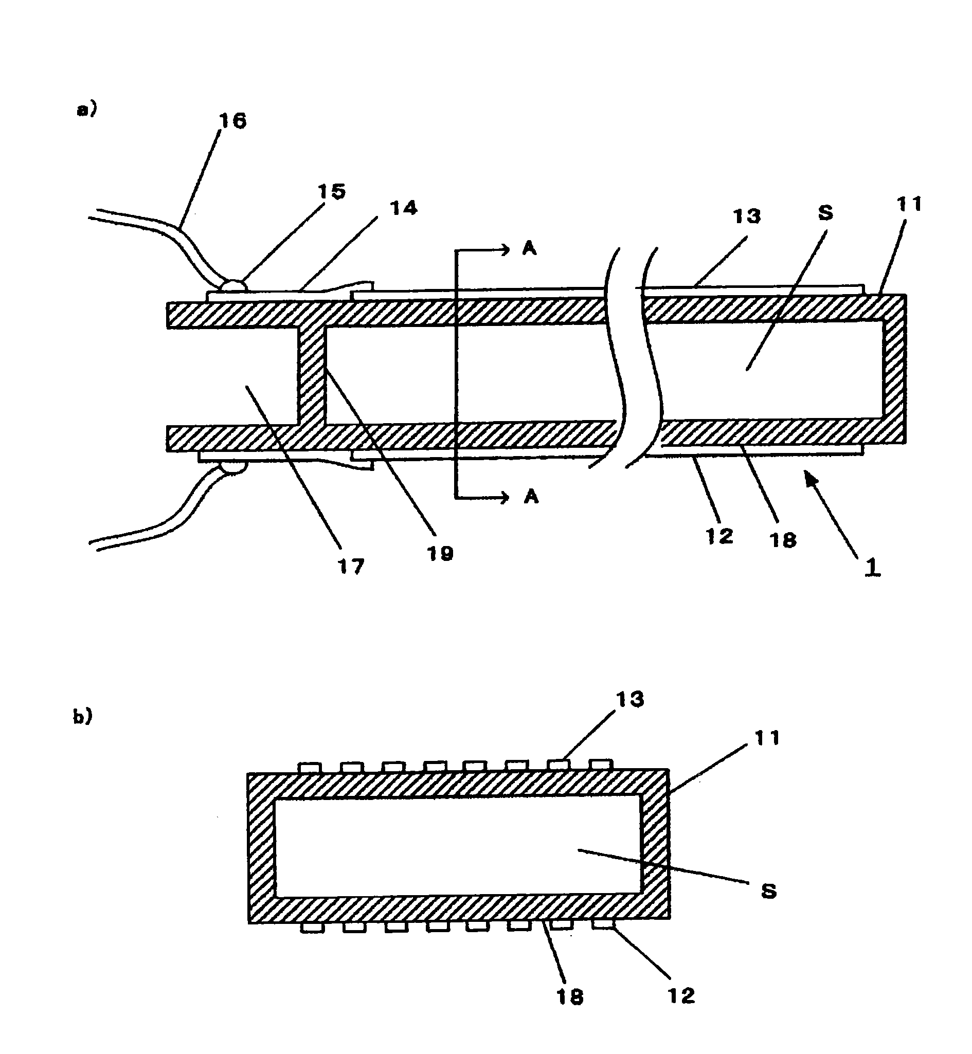
[0050] The first embodiment of the excimer lamp of the present invention is shown in figure 1 . figure 1-a) is a schematic cross-sectional view of the excimer lamp 1 of the present invention cut along the tube axis direction. The excimer lamp 1 is composed of a discharge vessel 11 made of quartz glass, an electrode 12 and an electrode 13 formed on the outer surface of the discharge vessel 11 at positions facing each other, and an electrode 13 formed inside the discharge vessel 11 and enclosed with a A discharge space S of gas such as xenon is used for discharge. In addition, although not shown in the figure, in the discharge space S, an ultraviolet reflective film is provided in addition to the window 18 for emitting light. The electrode 12 is made of, for example, a light-transmitting electrode made of grid-shaped printed electrodes, etc., and the surface of the discharge vessel 11 on which the electrode 12 is disposed serves as a window for emitting excimer light generat...

Embodiment 2

[0058] Figure 4 Shows the second embodiment of the present invention. Figure 4 -a) is a schematic cross-sectional view of the excimer lamp 20 according to the second embodiment of the present invention, taken along the axis of the lamp tube. The basic composition of the excimer lamp 20 and figure 1 The case of the first embodiment shown is the same, and the same reference numerals are assigned to the same components as in the case of the first embodiment. And, with figure 1 In the same manner as in the case of , an ultraviolet reflective film (not shown) is provided in the discharge space S. As shown in FIG. In this second embodiment, the space 21 connected to the discharge space S and divided by at least five surfaces is isolated from the outside by the outer wall 22 . In this embodiment, the interior of the space 21 is in a vacuum state, or is filled with a gas that is not easy to discharge, such as nitrogen. Accordingly, there is an advantage that no discharge occu...


PUM


Abstract

An excimer lamp is provided, which can suppress deterioration caused by oxidation of power supply wires for supplying electricity to the excimer lamp and the connection portion for connecting the power supply wires to the electrodes, improve reliability, and prolong life thereof. The excimer lamp of the invention includes an electrode provided outside the capacitor, gas for discharging is enclosed inside the discharging capacitor, medium is provided between the electrode and another electrode in the same pair with the electrode, conductive wires for supplying electricity between the electrodes are connected to the electrode and the other electrode, and electricity is supplied to the gas for discharging through the conductive wire, the electrode, and the medium. In the structure, a space connected to one terminal of the discharging capacitor and divided by at least five faces is provided, the space is isolated from the capacitor by an isolation wall, and a connection portion electrically connected to the electrode is formed outside the space. The conductive wires are connected to the connection portion through soldering tin.

Description

technical field [0001] The present invention relates to an optical cleaning device for a liquid crystal substrate, an ultraviolet treatment device for a semiconductor, and an excimer lamp used for a surface modification device of a resin irradiated with light. In particular, it relates to an excimer lamp characterized by a lamp structure connecting a portion of a power supply line that supplies power to the excimer lamp. Background technique [0002] Conventionally, an excimer lamp is known as an ultraviolet light source used in an optical cleaning device for a liquid crystal substrate, an ultraviolet treatment device for a semiconductor, or the like. In particular, in a device such as a xenon excimer lamp in the vacuum ultraviolet region where the light emitted by the excimer lamp is arranged, nitrogen gas is used to replace the inside of the housing constituting the lampshade for disposing the excimer lamp, and the inside of the housing is replaced with nitrogen gas. A li...

Claims


Application Information

Patent Timeline
Patent Type & Authority Patents(China)
IPC IPC(8): H01J61/04H01J65/00H01J61/30
CPCH01J5/50H01J5/54H01J5/58H01J61/35H01J61/36H01J65/046H05B41/2806
Inventor 竹添法隆远藤真一川口真孝
Owner USHIO DENKI KK
Why Eureka
Try Eureka