Automatic lifting mechanism

A technology of automatic lifting and driving device, applied in the direction of lifting device, electrical components, electric solid devices, etc., can solve the problems of the effective working stroke limited by oil volume, loud noise, fine dust particles, short service life, etc., and achieve a simple structure. Compact, high cleanliness, improved cleanliness effect

Inactive Publication Date: 2010-02-10
DONGGUAN ANWELL DIGITAL MASCH CO LTD
View PDF0 Cites 15 Cited by
  • Summary
  • Abstract
  • Description
  • Claims
  • Application Information

AI Technical Summary

Problems solved by technology

The hydraulic method has a relatively large jacking force and good self-locking performance, but the technical requirements for implementing this method are high, such as hydraulic lifting devices, which have complex structures, high processing accuracy requirements, good sealing performance, and require professionals for maintenance. The effective working stroke is limited by the amount of oil
Although the air pressure method has good self-locking performance, the lifting force is small. For example

Method used


Image

  • Automatic lifting mechanism
  • Automatic lifting mechanism

Examples


Embodiment Construction

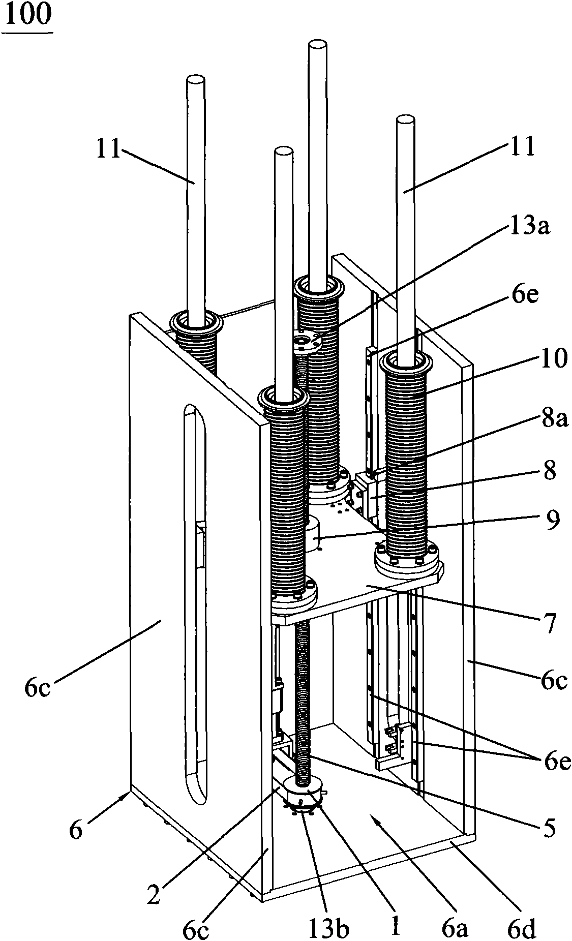
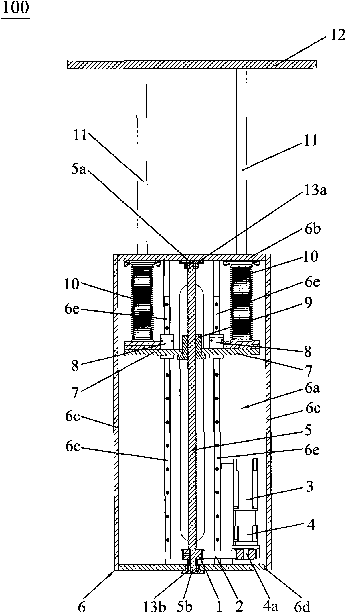
[0015] Such as figure 1 and figure 2 As shown, the automatic lifting mechanism 100 of the present invention includes a support box 6, a workbench 12, a pillar 11, a transmission device, a driving device and a control device (not shown in the figure), the support box 6 is a hollow structure, and the hollow structure forms Placement chamber 6a, one end of the pillar 11 passes through the top wall 6b of the support box 6 and is connected with the workbench 12, the other end of the pillar 11 is connected with the transmission device, and the drive device is connected with the The transmission device is accommodated in the placement cavity 6a, the drive device is connected to the transmission device, the control device is electrically connected to the drive device, the control device controls the drive device, and the drive device Drive the transmission device, the transmission device drives the pillar 11 to do linear reciprocating motion, wherein the transmission device includes...


PUM


Abstract

The invention discloses an automatic lifting mechanism comprising a supporting box, a working table, a supporting column, a transmission device, a driving device and a control device, wherein the supporting box is a hollow structure; the hollow structure forms an installing cavity; one end of the supporting column penetrates through the top wall of the supporting box and is connected with the working table; the other end of the supporting column is connected with the transmission device; the transmission device is installed in the installing cavity; the driving device is connected with the transmission device; the control device is electrically connected with the driving device; the control device controls the driving device which drives the transmission device; the transmission device drives the supporting column for linear reciprocating movement; the transmission device comprises a threaded rod, a nut and a supporting plate; the nut penetrates in the central position of the supporting plate; one end of the threaded rod penetrates through the nut and is meshed with the nut; the other end of the threaded rod is connected with the driving device; the driving device drives the threaded rod to rotate; the lateral wall of the supporting plate is provided with a slide block with a groove; the lateral wall of the supporting box is provided with a guiding rail; the guiding rail corresponds to the slide block and is parallel to the threaded rod and the guiding rail is clamped and connected with the groove of the slide block. The invention aims to provide the automatic lifting mechanism, which has high transmission precision, high cleanliness, low noise and simple and compact structure and is suitable for lifting finished products or semifinished products on the production lineof vacuum environmental industry.

Description

technical field [0001] The invention relates to a lifting mechanism, in particular to an automatic lifting mechanism for lifting finished or semi-finished products on a production line in a vacuum environment industry. Background technique [0002] With the continuous development of the economy, the continuous advancement of science and technology and the decrease of world energy, people pay more and more attention to energy conservation and utilization efficiency in production, so that the harmonious development of man and nature can meet the requirements of China's new industrialization road. [0003] For example, in the display industry of digital products that require a very high vacuum environment, in order to save energy and reduce production costs, enterprises have increased investment in research and development, and are constantly pursuing new energy-saving products. Among them, OLED display is a new product in digital products. OLED is Organic Light-Emitting Diode ...

Claims


Application Information

Patent Timeline
IPC IPC(8): B66F3/10H01L51/56
Inventor 杨明生范继良郭业祥王曼媛王勇
Owner DONGGUAN ANWELL DIGITAL MASCH CO LTD
Why Eureka
Try Eureka