High-power LED light fitting based on MEMS micro-cooling device radiation

A technology of LED lamps and cooling devices, which is applied in the direction of cooling/heating devices of lighting devices, lighting devices, lighting and heating equipment, etc., which can solve the problems of difficulty in guaranteeing service life, affecting the use effect, and unsatisfactory heat dissipation effect of high-power LED lamps, etc. problem, to achieve the effect of compact structure, improved heat dissipation efficiency, and good heat dissipation effect

Inactive Publication Date: 2010-02-10
JIANGSU MINGJIAHUI ELECTRICAL EQUIP
View PDF0 Cites 15 Cited by
  • Summary
  • Abstract
  • Description
  • Claims
  • Application Information

AI Technical Summary

Problems solved by technology

[0009] The purpose of the present invention is to provide a high-power LED lamp based on MEMS micro-cooling device for heat dissipation due to the un

Method used


Image

  • High-power LED light fitting based on MEMS micro-cooling device radiation
  • High-power LED light fitting based on MEMS micro-cooling device radiation
  • High-power LED light fitting based on MEMS micro-cooling device radiation

Examples


Example Embodiment

[0023] Example one.

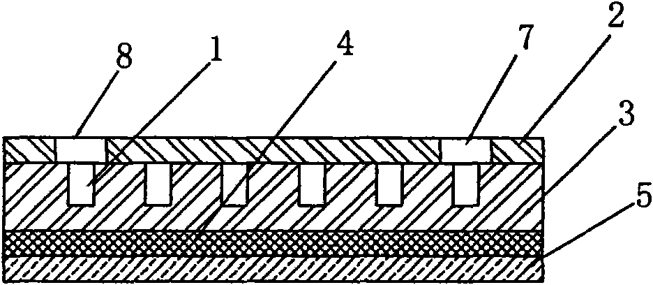
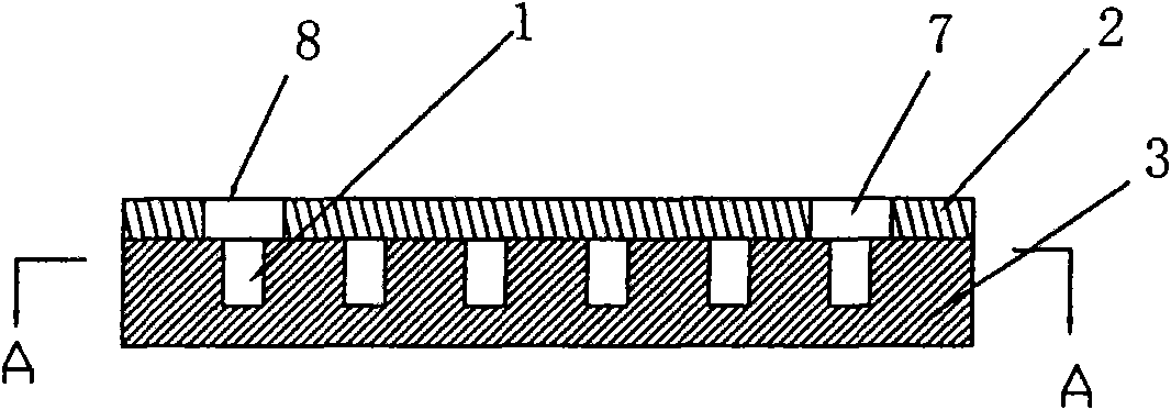
[0024] Such as figure 1 , 3 , 4 shown.

[0025] A high-power LED lamp based on the heat dissipation of a MEMS micro-cooling device includes a PCB board 5 for mounting LED chips. The side of the PCB board 5 on which the LED chip is not mounted is connected to the bottom of the diamond substrate 3. The diamond substrate 3 is provided with a continuous S-shaped microfluidic heat dissipation channel 1 (such as Figure 4 ), a sealing plate 2 is installed on the microfluidic heat dissipation channel 1, and the sealing plate 2 is provided with a microfluidic inlet 7 and a microfluidic outlet 8 communicating with the microfluidic heat dissipation channel 1. The flow takes away the heat emitted and conducted to the diamond substrate 3 during the use of the LED chip. In specific implementation, the diamond substrate 3 can be bonded and connected to the PCB board 5 where the LED chip is mounted through the thermally conductive glue 4, such as figure 1 Shown. The micro...

Example Embodiment

[0026] Example two.

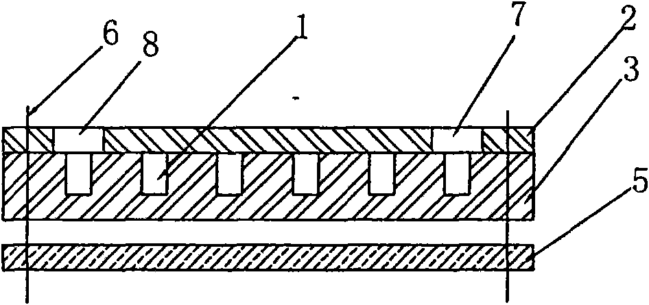
[0027] Such as figure 2 , 3 , 4 shown.

[0028] A high-power LED lamp based on the heat dissipation of a MEMS micro-cooling device includes a PCB board 5 for mounting LED chips. The side of the PCB board 5 on which the LED chip is not mounted is connected to the bottom of the diamond substrate 3. The diamond substrate 3 is provided with a continuous S-shaped microfluidic heat dissipation channel 1 (such as Figure 4 ), a sealing plate 2 is installed on the microfluidic heat dissipation channel 1, and the sealing plate 2 is provided with a microfluidic inlet 7 and a microfluidic outlet 8 communicating with the microfluidic heat dissipation channel 1. The flow takes away the heat emitted and conducted to the diamond substrate 3 during the use of the LED chip. During specific implementation, the diamond substrate 3 can be bonded and connected to the PCB board 5 where the LED chip is mounted through the connecting bolt 6, such as figure 2 Shown. The microflui...


PUM

PropertyMeasurementUnit
Heightaaaaaaaaaa

Abstract

The invention relates to a high-power LED light fitting based on MEMS micro-cooling device radiation, comprising a PCB (5) used for installing an LED chip. The high-power LED light fitting is characterized in that one surface of the PCB (5), which is not provided with the LED chip, is connected with the bottom of a diamond basal body (3); a microfluid radiation channel (1) is arranged on the diamond basal body (3); a sealing board (2) is arranged on the microfluid radiation channel (1); and a microfluid inlet (7) and a microfluid outlet (8) which are communicated with the microfluid radiationchannel (1) is arranged on the sealing board (2). Heat emitted and conducted to the diamond basal body (3) during the use of the LED chip is taken away by the flow of microfluid on the microfluid radiation channel (1). The invention has reasonable design, compact structure, easy manufacture and good radiation effect. The heat emitted when a super-power LED works can be quickly transferred, so theradiation demand of the high-power LED light fitting can be effectively satisfied, and industrial large scale production can be realized on super-power LED street lights. Experiments prove that the radiation efficiency can be increased by more than 50%.

Description

technical field [0001] The invention relates to a high-power LED lamp, especially a design and manufacturing process of a high-power LED lamp that integrates microfluidic control technology, micro-electromechanical system, micro-heat exchange technology and LED lamp manufacturing technology. It belongs to micro-manufacturing, The technical field where surface modification technology and micro-optical technology intersect, specifically a high-power LED lamp based on MEMS micro-cooling device for heat dissipation. Background technique [0002] With the rise of gallium nitride-based third-generation semiconductors and the successful research of blue and white light-emitting diodes, semiconductor lighting has brought another leap in the history of human lighting. Compared with incandescent lamps and fluorescent lamps, LED has become one of the main development directions of a new generation of environmentally friendly lighting sources because of its small size, full solid state,...

Claims


Application Information

Patent Timeline
IPC IPC(8): F21S2/00F21V29/00H01L23/473F21Y101/02F21Y103/10F21Y115/10
Inventor 朱纪军洪思忠樊世才
Owner JIANGSU MINGJIAHUI ELECTRICAL EQUIP
Why Eureka
Try Eureka