Internal operation image real-time monitoring system for high-voltage electric apparatus

A technology for high-voltage electrical equipment and image monitoring, applied in closed-circuit television systems, television systems adapted to optical transmission, radiation pyrometry, etc., can solve the shortage of monitoring techniques, indirect diagnostic methods, and inability to meet the technical requirements of equipment condition maintenance To prevent and control abnormalities and accidents, improve operation level and power supply reliability, and have strong anti-interference ability

Active Publication Date: 2010-02-10
PINGDINGSHAN POWER SUPPLY ELECTRIC POWER OF HENAN +1
View PDF0 Cites 17 Cited by
  • Summary
  • Abstract
  • Description
  • Claims
  • Application Information

AI Technical Summary

Problems solved by technology

[0009] In order to solve the problem that the existing high-voltage electrical equipment monitoring technology is insufficient, the diagnostic method is not direct, and cannot meet the technical requirements of equipment condition maintenance, in view of this, the purpose of the present invention is to provide an internal image monitoring system for high-voltage electrical The internal parts of the high-voltage equipment in operation are loose or fall off, deformed, partial discharge, hot spots, oil and gas material colors, etc., for direct observation and monitoring. Various optical fiber sensors of the system can also be used to monitor the oil, gas, etc. inside the equipment. Real-time monitoring of non-electricity measurement data to achieve real-time holographic images and non-electricity monitoring of high-voltage electrical equipment in operation

Method used


Image

  • Internal operation image real-time monitoring system for high-voltage electric apparatus
  • Internal operation image real-time monitoring system for high-voltage electric apparatus

Examples


Embodiment Construction

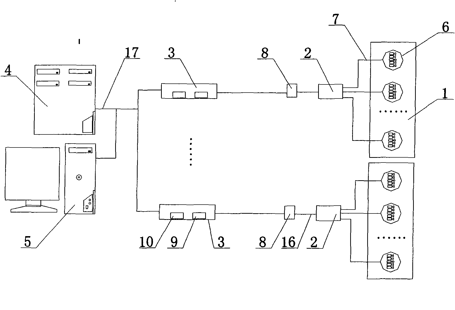
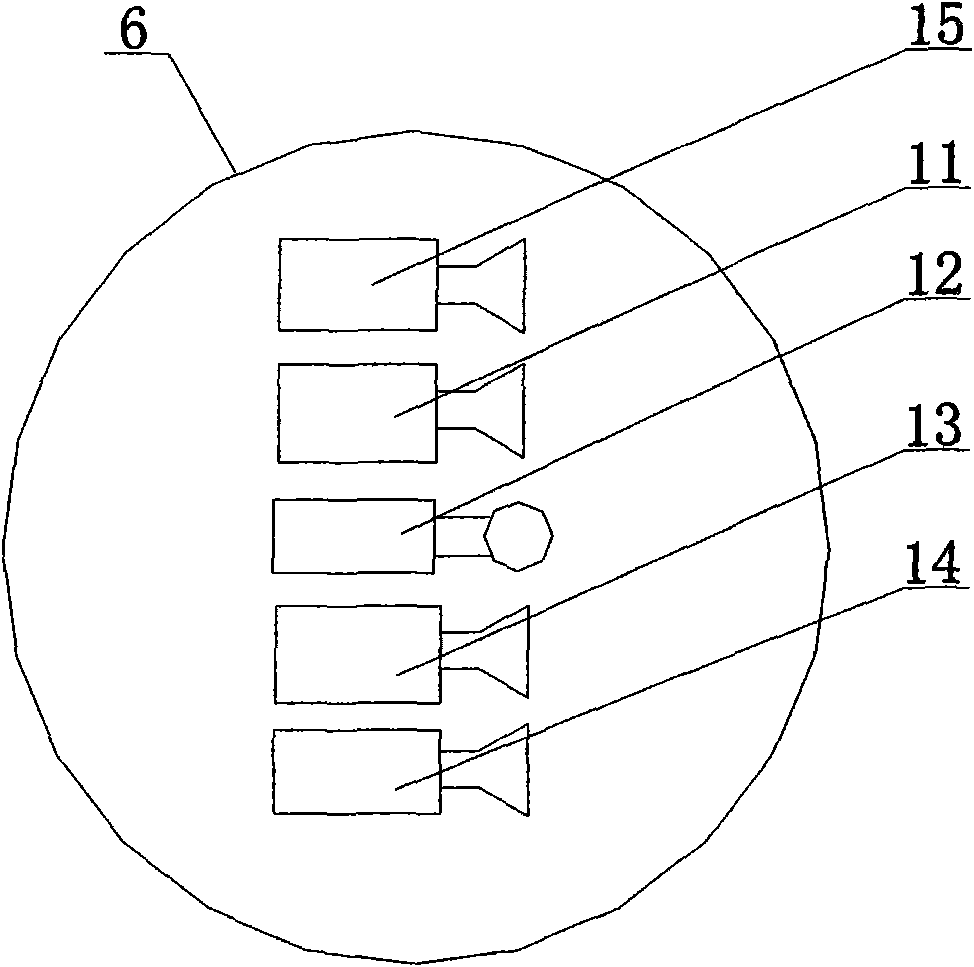
[0019] Depend on figure 1 It can be seen that the real-time monitoring system for the internal operation image of the high-voltage electrical equipment mainly includes high-voltage equipment 1, an optical cable hub 2, an industrial computer 3, a computer server 4, and a computer terminal 5. The monitoring point 6 is connected with the high-voltage insulated optical cable 7 between each monitoring point 6 and the optical cable hub 2. In the optical cable hub 2, each high-voltage insulated optical cable 7 is connected, and the high-voltage insulated optical cable is connected through the optical cable outlet sleeve 8. 7 is led out of the high-voltage equipment 1, and is connected to the industrial computer 3 in the main control room of the substation through an insulated optical cable 16. The industrial computer 3 is equipped with a light source device 10 and a photoelectric conversion device 9, and the industrial computer 3 is connected to the computer server 4 and the computer ...


PUM


Abstract

The invention discloses an internal operation image real-time monitoring system for high-voltage electric apparatus, which mainly comprises a high-voltage apparatus, an optical cable hub, an industrial computer, a computer server and a computer terminal, wherein the inner wall of the cavity of the high-voltage apparatus is provided with a monitoring point; the monitoring point mainly comprises a high-resolution optical-fiber lens, an infrared optical-fiber lens, an ultraviolet optical-fiber lens, an optical-fiber lamp and an optical-fiber sensor; the monitoring point is provided with a high-voltage insulating optical cable and an afflux optical cable hub; an optical cable outlet sleeve is arranged behind the optical cable hub; and the high-voltage insulating optical cable is led out of thehigh-voltage apparatus through the optical cable outlet sleeve and connected with the computer server of the main control room of a transforming plant through the industrial computer. The system canmonitor data information in an apparatus in real time, such as electrical quantities and the like, and has the advantages of high precision, strong disturbance resisting capacity and high response speed. When apparatus abnormalities and faults happen, the system can provide detailed information before and after the abnormality or fault, which is helpful to analyze the accident and make the corresponding measures, and enhance the operation level and the power supply reliability of the electric apparatus.

Description

technical field [0001] The invention relates to a real-time monitoring system, in particular to a real-time monitoring system for internal operation images of high-voltage electrical equipment. Background technique [0002] Substation high-voltage electrical equipment has the characteristics of intensive technology and high price. For example, the cost of a large transformer is more than 10 million yuan, and the main electrical equipment such as transformers, circuit breakers, and GIS generally adopt closed oil insulation or SF6 gas insulation. Whether it is in operation or in an accident, it is impossible to directly see its internal conditions. From the power outage maintenance system after an accident in the 1950s, it has gradually evolved into a maintenance preventive system and a power outage preventive test system. The above methods and systems all affect the utilization of equipment. Efficiency and reliability of power supply, the concept of condition-based maintenanc...

Claims


Application Information

Patent Timeline
Patent Type & Authority Applications(China)
IPC IPC(8): G01R31/02G01R31/12G01J5/00G01B11/16G01J3/46H04N7/18H04N7/22
Inventor 智勇军张力淼肖承仟段华明王俊良
Owner PINGDINGSHAN POWER SUPPLY ELECTRIC POWER OF HENAN
Why Eureka
Try Eureka