Fountain aeration spray head and manufacture method and use method thereof
A nozzle and aeration technology, applied in water aeration, chemical instruments and methods, sustainable biological treatment, etc., can solve the problems of changing the aeration method, occupying a large area, and the flocs are not easy to rise.
- Summary
- Abstract
- Description
- Claims
- Application Information
AI Technical Summary
Problems solved by technology
Method used
Image
Examples
Embodiment 1
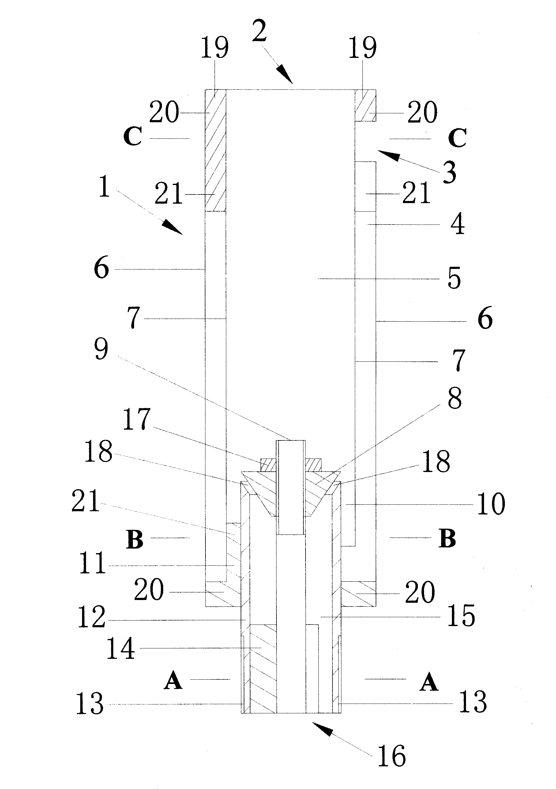
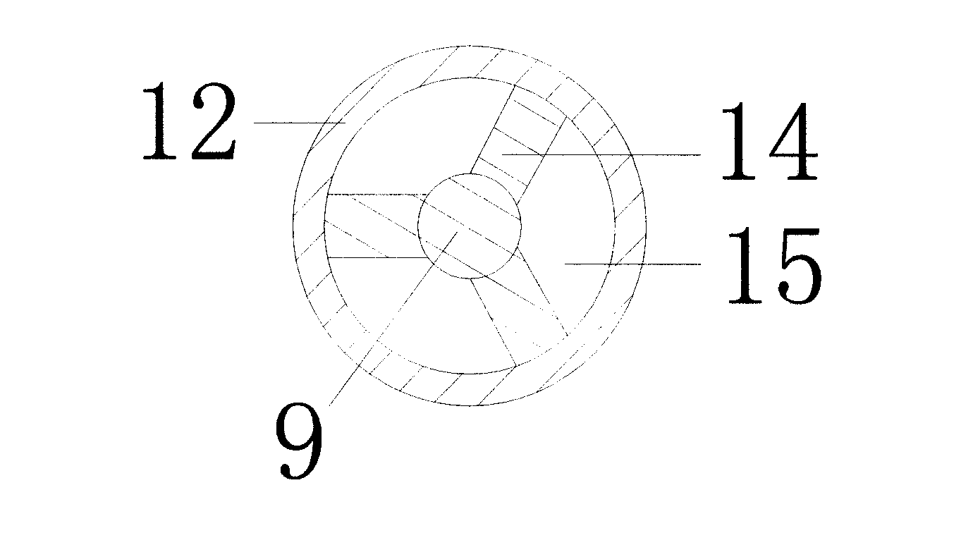
[0074] The main body of the nozzle (1) is composed of the outer barrel of the nozzle (6), the inner barrel of the nozzle (7), the air-water mixing diversion chamber (5), the water source nozzle (12) and the flow regulator (9), through the conical diversion bracket (14), the lower end flange support (11) and the upper end flange support (19) are connected to form the nozzle main body (1). The lower end of the nozzle (12) is equidistantly provided with at least 3 conical deflector supports (14), and the two sides of the conical deflector supports (14) are respectively connected to the inner wall of the water source nozzle (12) and the flow regulator. (9) The outer wall is fixedly connected, and the flow regulator (9) is fixedly arranged in the middle part of the water source nozzle (12) by the cone-shaped deflector support (14).
[0075] The conical deflector bracket (14) separates the water inlet channel (15) in the water source nozzle (12), and the water source enters the wate...
Embodiment 2
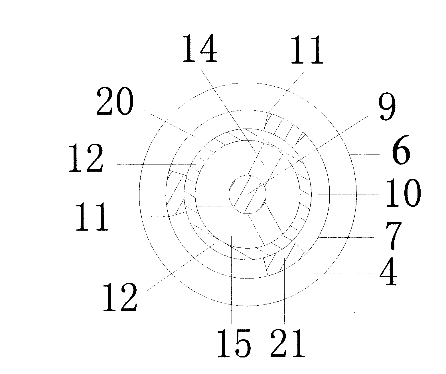
[0080] The outer wall of the water source nozzle (12) is fixedly provided with a lower end flange support (11) around the outer wall, and the bottom of the lower end flange support (11) is an annular closed plate (20) in the shape of an eye ring, along the inner side of the annular closed plate (20). At least three flange plates (21) are equidistantly arranged, and the flange plates (21) protrude on the annular closing plate (20), and the outer side of the annular closing plate (20) forms a raised platform, and the flange plates (21) form a A concave notch, the concave notch constitutes an air outlet (10), and the inner side of the lower end flange support (11) is fixedly connected with the outer wall of the water source nozzle (12).
[0081] The nozzle inner barrel (7) and the nozzle outer barrel (6) are hollow cylindrical, the diameter of the nozzle inner barrel (7) is smaller than the diameter of the nozzle outer barrel (6), the nozzle inner barrel (7) is arranged in the noz...
Embodiment 3
[0085] The upper end of the nozzle inner barrel (7) and the upper end of the nozzle outer barrel (6) are provided with an upper end flange support (19), and one end of the upper end flange support (19) is an annular closing plate (20) which is in the shape of an eye ring and is annularly closed. At least three flange plates (21) are equidistantly arranged on the plate (20), and the flange plates (21) protrude on the annular closed plate (20), and there are concave gaps between the flange plates (21), and the concave gaps Constitute the air inlet (3).
[0086] The outer wall of the upper end of the nozzle inner barrel (7) is fixedly connected with the inner side of the upper end flange support (19), and the inner wall of the upper end of the nozzle outer barrel (6) is fixedly connected with the outer side of the upper end flange support (19). The annular closing plate (20) of the flange support (19) closes the air intake channel (4) formed by the upper end of the inner barrel (...
PUM
 Abstract
Description
Claims
Application Information
 - R&D
- Intellectual Property
- Life Sciences
- Materials
- Tech Scout
- Unparalleled Data Quality
- Higher Quality Content
- 60% Fewer Hallucinations
Browse by: Latest US Patents, China's latest patents, Technical Efficacy Thesaurus, Application Domain, Technology Topic, Popular Technical Reports.
© 2025 PatSnap. All rights reserved.Legal|Privacy policy|Modern Slavery Act Transparency Statement|Sitemap|About US| Contact US: help@patsnap.com


