Device and method for pouring concrete continuous wall along gob-side entry in mining face

A technology of pouring concrete and retaining roadways, which is applied to mining equipment, shaft equipment, earthwork drilling and mining, etc. It can solve problems such as tight connection of roofs in difficult coal seams, a large amount of manpower and material resources, and concrete that is prone to leakage of grout, and achieves good roofing effect, High labor efficiency and good sealing effect

Active Publication Date: 2011-12-28
SHAANXI PIONEERING ARCHITECTURAL TECH
View PDF0 Cites 2 Cited by
  • Summary
  • Abstract
  • Description
  • Claims
  • Application Information

AI Technical Summary

Problems solved by technology

[0002] Traditional mining face gobside entry retention uses wooden piles, dense pillars, gangue bags, material stone walls or concrete diaphragm walls, while the concrete diaphragm walls use rigid formwork to set up the formwork. The construction disadvantages of these methods are that they require a lot of manpower and material resources , and the labor intensity is high, and the construction speed is slow; the rigid formwork is not easy to change with the change of the slope surface of the roof and floor, resulting in poor airtightness, easy grout leakage during the concrete pouring process, and the poured concrete is not dense, and it is difficult to be tightly combined with the coal seam roof

Method used


Image

  • Device and method for pouring concrete continuous wall along gob-side entry in mining face
  • Device and method for pouring concrete continuous wall along gob-side entry in mining face
  • Device and method for pouring concrete continuous wall along gob-side entry in mining face

Examples


Embodiment Construction

[0022] Below in conjunction with accompanying drawing, content of the invention is further described:

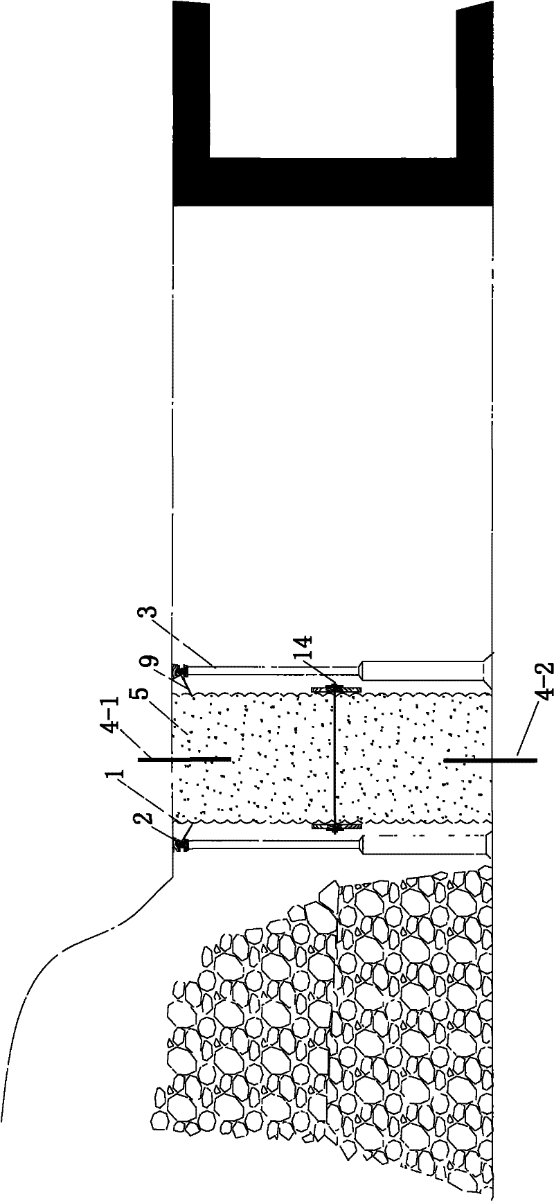
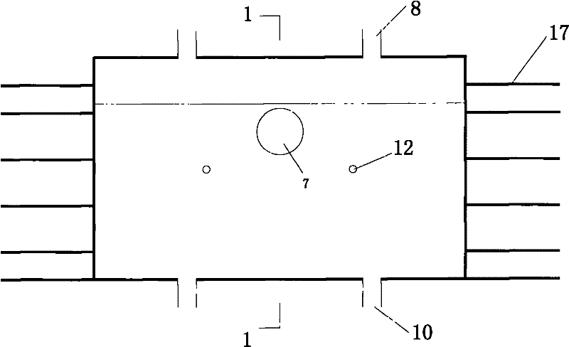
[0023] refer to Figure 1-Figure 4 As shown: a fiber flexible formwork 1 is composed of a main formwork 15 and a top formwork 16. The two sides of the fiber flexible formwork are respectively connected to the flange 9, and the flange 9 is equipped with a sleeve 11, and the sleeve 11 is penetrated with a The steel beam 2 and the flange 9 hang the fiber flexible formwork 1 on the coal seam roof through the single hydraulic prop 3 or the anchor rod 6, and the fiber flexible formwork 1 is respectively connected to the pouring port 7, the upper reinforcement opening 8, and the lower reinforcement reinforcement in turn. Port 10, limit hole 12, one end of the upper planting bar 4-1 is connected to the coal seam roof, the other end is inserted into the fiber flexible formwork 1 through the upper planting bar port 8 and fixedly connected with the concrete 5, and one end of the lower ...


PUM


Abstract

The invention discloses a device and a method for pouring a concrete continuous wall along a gob-side entry in a mining working face. The shape of the fiber flexible formwork is a cuboid or a cube, and it is composed of a main formwork and a roof formwork. The fiber flexible formwork is connected with flanges, pouring ports, planting ribs, limit holes, and tie bars. The fiber flexible formwork is prefabricated, and the flange hangs the flexible formwork on the coal seam roof through a single hydraulic prop or anchor rod. The ends are fixed with pallet nuts, the concrete delivery pipe is inserted into the filling port and tied, and the concrete pump is used to inject concrete into the flexible formwork through the delivery pipe to form a concrete continuous wall. The structure is simple, the construction speed is fast, the labor efficiency is high, the airtightness is good, the grout is not easy to leak, the concrete filling is dense, the roofing effect is good, the mechanized operation, adapt to the change of the slope of the roof and the floor, widely used in coal mines, metallurgical mines, water conservancy, underground construction , defense and other industries.

Description

technical field [0001] The invention relates to a concrete continuous wall, in particular to a device and a method for pouring a concrete continuous wall along a gob-side entry in a mining working face. Background technique [0002] Traditional mining face gobside entry retention uses wooden piles, dense pillars, gangue bags, material stone walls or concrete diaphragm walls, while the concrete diaphragm walls use rigid formwork to set up the formwork. The construction disadvantages of these methods are that they require a lot of manpower and material resources , and the labor intensity is high, and the construction speed is slow; the rigid formwork is not easy to change with the change of the slope surface of the roof and floor, resulting in poor airtightness, easy grout leakage during the concrete pouring process, and the poured concrete is not dense, and it is difficult to be tightly combined with the coal seam roof . Contents of the invention [0003] The purpose of th...

Claims


Application Information

Patent Timeline
Patent Type & Authority Patents(China)
IPC IPC(8): E21D11/10E21D11/12
Inventor 王晓利吴玉意
Owner SHAANXI PIONEERING ARCHITECTURAL TECH
Why Eureka
Try Eureka