Fan assembly

A fan and air volume technology, applied in the direction of instruments, electrical digital data processing, digital data processing components, etc., can solve the problems of reducing fan efficiency and fan airflow cannot be effectively used, and achieve the effect of improving efficiency

Inactive Publication Date: 2010-02-17
COMPAL ELECTRONICS INC
View PDF0 Cites 15 Cited by
  • Summary
  • Abstract
  • Description
  • Claims
  • Application Information

AI Technical Summary

Problems solved by technology

Therefore, if a high-speed airflow is to be provided for a specific area (such as a certain part of an electronic component), the fan speed can only be increased, but this also causes the airflow generated by the fan to not be used effectively, thereby reducing the efficiency of the fan

Method used


Image

  • Fan assembly
  • Fan assembly
  • Fan assembly

Examples


Embodiment Construction

[0109] In order to make the above-mentioned features and advantages of the present invention more comprehensible, the following specific embodiments are described in detail with reference to the accompanying drawings.

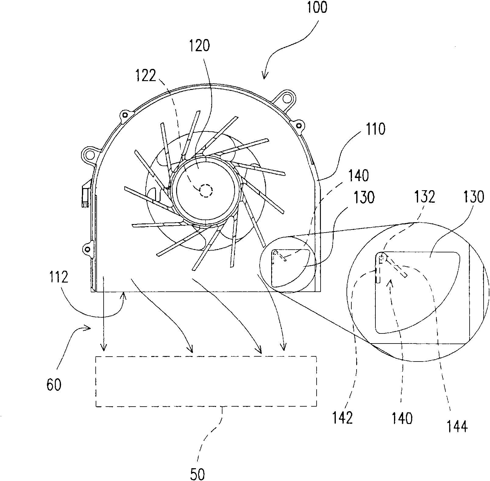
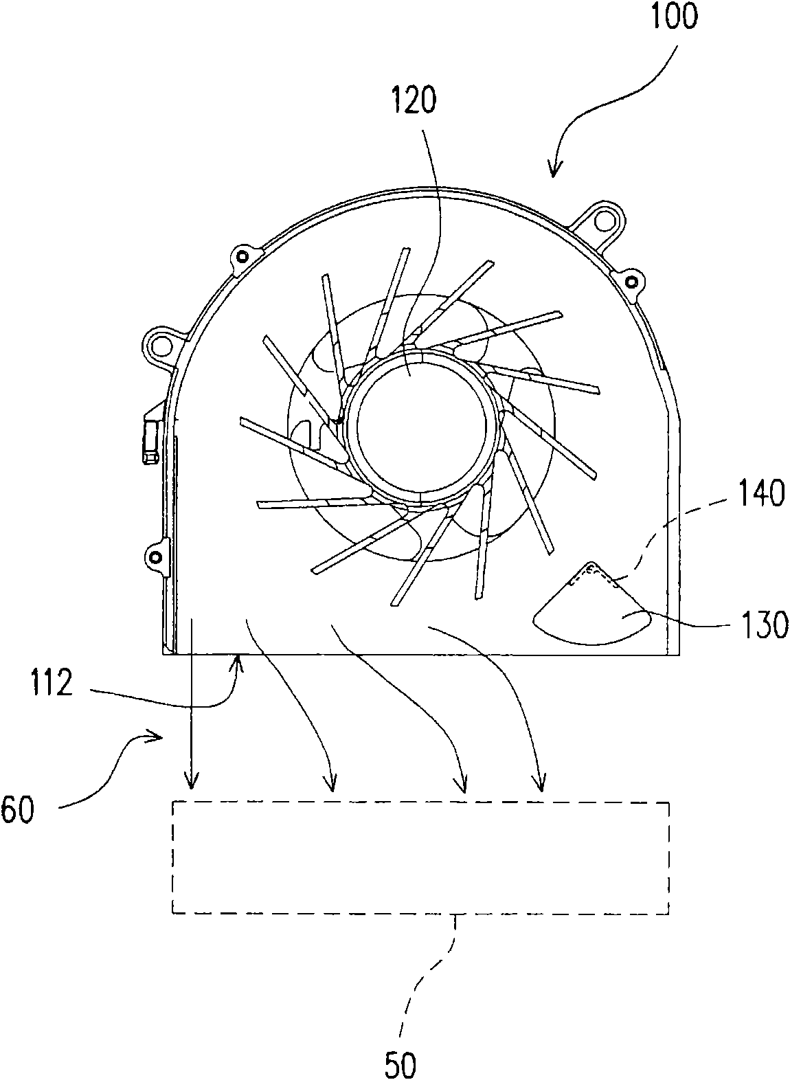
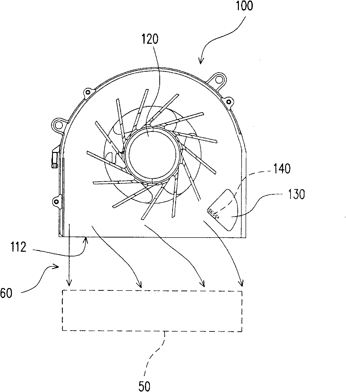
[0110] Figure 1A to Figure 1C It is a schematic diagram of a fan assembly in an embodiment of the present invention. It should be noted that, in order to make the drawings clear, only part of the casing is shown in the following drawings, and those skilled in the art can implement according to the requirements according to the content described in the present invention. Please refer to Fig. 1 first, the fan assembly 100 includes a casing 110, a fan 120, a throttle valve 130 and a reset member 140, wherein the fan 120 includes a rotating shaft 122 and can be a centrifugal fan or an axial flow fan. In this embodiment, the fan 120 used is a centrifugal fan and the reset member 140 can be regarded as a component of a regulator. The casing 110 has an air outlet 1...


PUM


Abstract

The invention discloses a fan assembly applied to an electronic device. The fan assembly comprises a housing, a fan, a throttle valve and a regulator. The housing is provided with an air outlet. The fan is arranged in the housing, and is applicable to providing air current, wherein, the air current produces air flow at the air outlet. The throttle valve is movably arranged in the housing, and located at the air outlet. The regulator is connected to the throttle valve for controlling the motion of the throttle valve to regulate opening size of the air outlet.

Description

technical field [0001] The present invention relates to a fan assembly, and in particular to a fan assembly applied to an electronic device. Background technique [0002] In recent years, portable electronic devices are developing towards miniaturization and multi-function. Portable electronic devices with more powerful functions usually have higher speed chips. However, the higher the speed of the chip, the more heat energy it will generate, coupled with the miniaturization of the portable electronic device, these factors make the heat dissipation capability of the portable electronic device very important. [0003] A fan is a fairly common component in electronic heat dissipation technology. It usually cooperates with heat dissipation fins to dissipate heat from high-power components to keep the temperature of the components within their operating temperature range. In addition, the active airflow generated by the fan can convect the interior of the electronic device with...

Claims


Application Information

Patent Timeline
Patent Type & Authority Applications(China)
IPC IPC(8): F04D29/00F04D29/40F04D27/00F04D25/08G06F1/20
Inventor 田奇伟林春宏苏建铭吴文瑜林明源
Owner COMPAL ELECTRONICS INC
Why Eureka
Try Eureka