
Refrigerating air-conditioner device

An air-conditioning device and refrigerant technology, which is applied in the direction of refrigerators, refrigeration and liquefaction, lighting and heating equipment, etc., can solve problems such as limiting the application range, reducing the heat exchange efficiency of the evaporator 50, and missing applications, so as to avoid frosting or condensation ice effect

Inactive Publication Date: 2010-02-17
飞杰能源开发股份有限公司
View PDF0 Cites 5 Cited by
  • Summary
  • Abstract
  • Description
  • Claims
  • Application Information

AI Technical Summary

Problems solved by technology

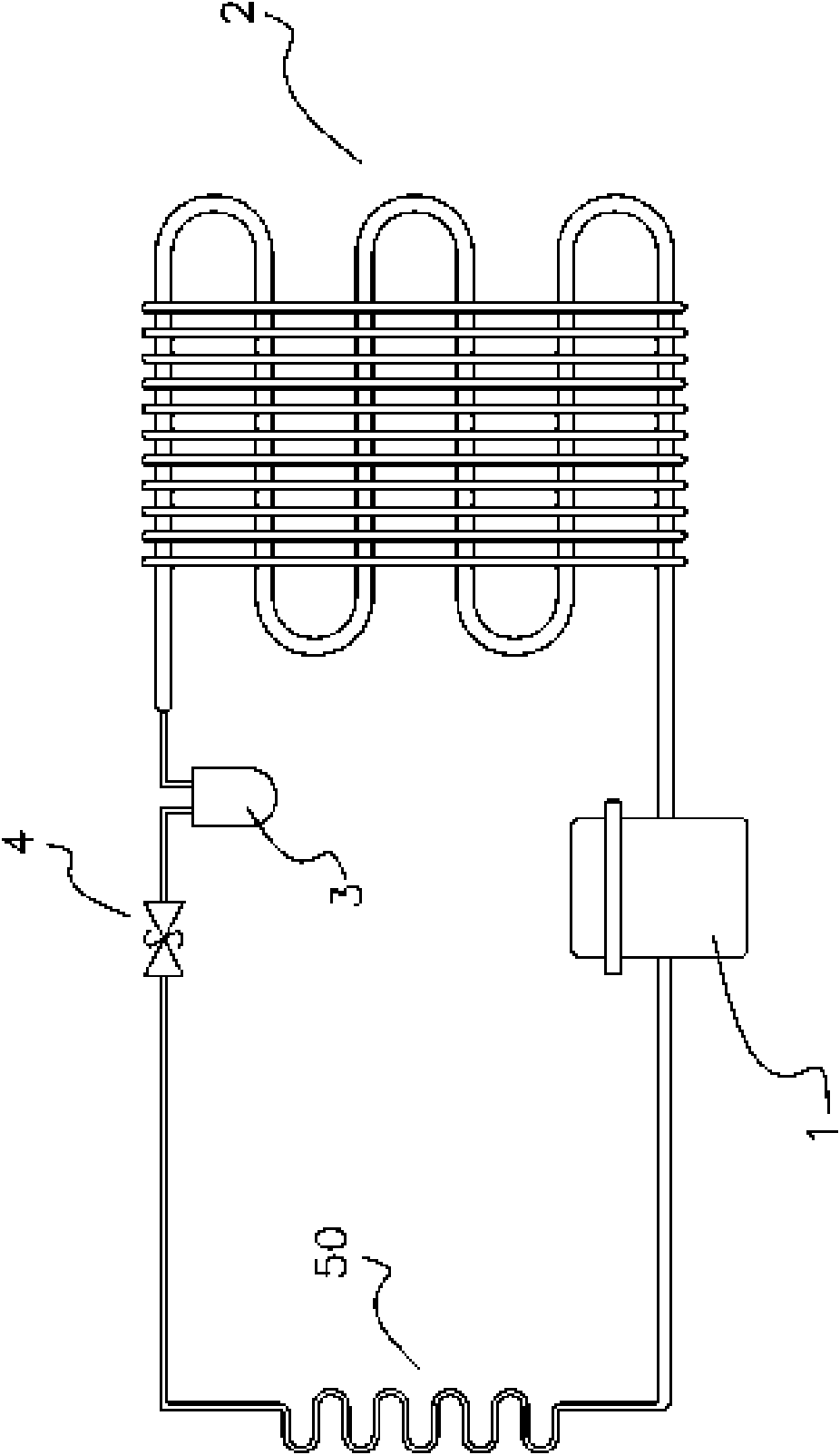
[0003] Yet, because under the environment of atmospheric pressure, the water vapor in the air can condense into liquid water when the temperature of 4 ℃, and condenses into frost or ice when the temperature of 0 ℃, therefore, the above-mentioned traditional structure is applied to hot water. In a humid environment, it is often necessary to set the working temperature of the evaporator 50 above 4°C or below 0°C (for freezing), which not only severely limits the overall application range, but also the solidified frost or ice will cause The surface of the evaporator 50 is isolated from the external environment and cannot continue the heat exchange action, which seriously reduces the heat exchange efficiency of the evaporator 50, thereby causing a serious lack of application

Method used


Image

  • Refrigerating air-conditioner device
  • Refrigerating air-conditioner device
  • Refrigerating air-conditioner device

Examples


Embodiment Construction

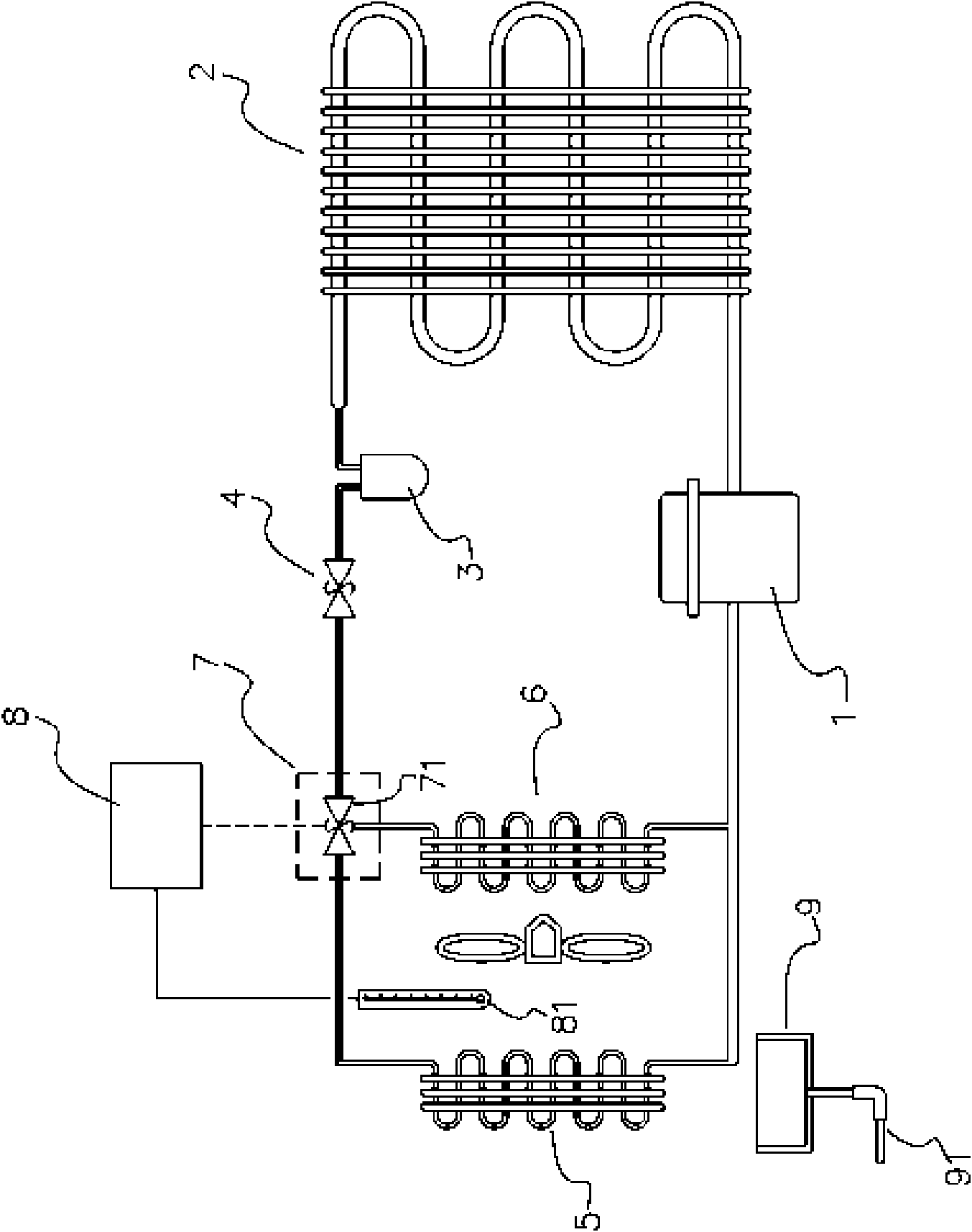
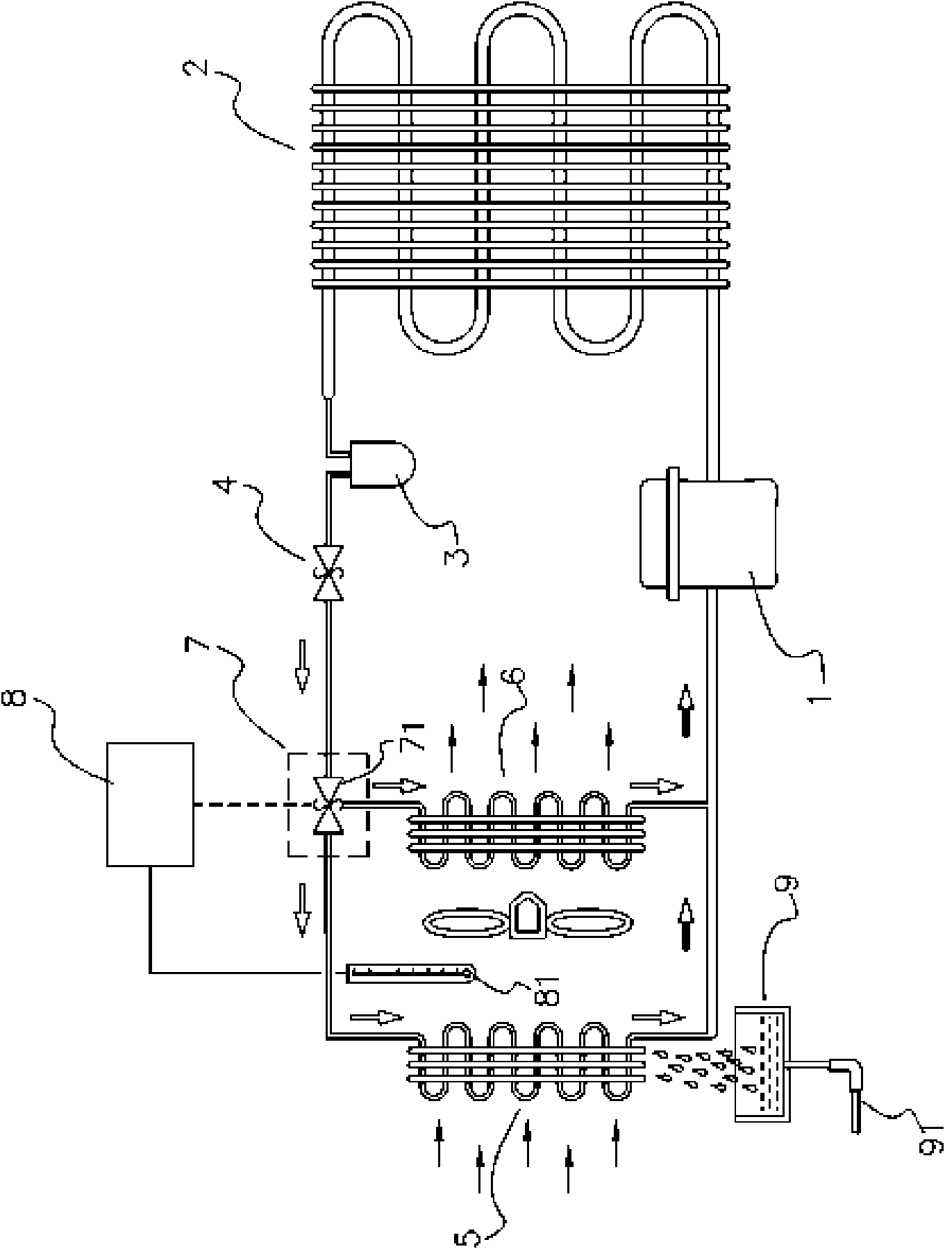
[0038] figure 2 It is a schematic diagram of the structure of the first embodiment of the present invention, by which image 3 It can be clearly seen that the structure of the first embodiment of the present invention mainly includes: compressor 1, condenser 2, dryer 3, expansion valve 4, first evaporator 5, second evaporator 6 , the refrigerant control unit 7 and the control device 8, etc., wherein the compressor 1 compresses the refrigerant in the pipeline into a high-temperature and high-pressure gaseous state. 3 Absorb moisture, limit its flow rate by the expansion valve 4, and then introduce it into the first and second evaporators (5, 6) respectively through the refrigerant control unit 7 (which can be a three-way control valve 71), and through the refrigerant control unit 7 (Three-way control valve 71) can control the amount of refrigerant flowing into the first and second evaporators (5, 6) respectively, so as to set the working temperature of the first evaporator 5 ...


PUM


Abstract

A refrigerating air-conditioner device is disclosed. A compressor is used for compressing a coolant into high temperature high pressure gas state, a condenser is introduced for radiation, so that thecoolant can be subject to heat release and liquefaction, then an expansion valve is used for restricting liquid coolant output by the condenser to pass through a first evaporator and a second evaporator in trace flow and to be subject to heat absorption and vaporization, the working temperature of the first evaporator is kept between 0 DEG C and 4 DEG C, so that the moisture in the air passing through the first evaporator is condensed into liquid state water and discharged, drier air passes through the second evaporator, and the working temperature of the second evaporator is kept below 0 DEGC, so that the flowing air is fast cooled, and finally the vaporized low pressure gas state coolant is led back into the compressor to form circulation; therefore, the situation of frosting or icing of the evaporators caused by condensed water in high humidity environment can be effectively avoided, thus effectively improving overall heat exchange efficiency.

Description

technical field [0001] The invention relates to a refrigeration and air conditioning device. Background technique [0002] Traditionally, the structure of refrigeration or air-conditioning units has generally been seen, such as figure 1 As shown, it has an evaporator 50, a condenser 2, a compressor 1, an expansion valve 4 (capillary tube) and a drier 3 (if necessary), which uses the compressor 1 to compress the refrigerant in the pipeline It is a high-temperature and high-pressure gaseous state. The high-temperature and high-pressure refrigerant turns into a liquid state at room temperature through the heat generated by the condenser 2, and absorbs moisture through the dryer 3. The flow is limited by the expansion valve 4 (capillary) and then introduced into the evaporator 50. The evaporator 50 absorbs heat and vaporizes (the airflow can be driven by a fan to accelerate its heat absorption action), so that its pressure drops and vaporizes into a low-pressure gaseous state, ...

Claims


Application Information

Patent Timeline
Patent Type & Authority Applications(China)
IPC IPC(8): F25B5/02
Inventor 杨盛杰
Owner 飞杰能源开发股份有限公司
Learn More