Optical detection method of verticality error of longitudinal axis and latitudinal axis of horizontal type telescope

A telescope and horizontal technology, applied in the direction of using optical devices, measuring devices, instruments, etc., can solve problems such as inappropriate promotion and complicated calculation process, and achieve the effect of reliable measurement method, simple method principle and easy realization.

Inactive Publication Date: 2010-02-17
CHANGCHUN INST OF OPTICS FINE MECHANICS & PHYSICS CHINESE ACAD OF SCI
View PDF0 Cites 19 Cited by
  • Summary
  • Abstract
  • Description
  • Claims
  • Application Information

AI Technical Summary

Problems solved by technology

This method requires the installation of an optical system, the calculation process is complicated, and the exact position of the

Method used


Image

  • Optical detection method of verticality error of longitudinal axis and latitudinal axis of horizontal type telescope
  • Optical detection method of verticality error of longitudinal axis and latitudinal axis of horizontal type telescope
  • Optical detection method of verticality error of longitudinal axis and latitudinal axis of horizontal type telescope

Examples


Embodiment Construction

[0017] The present invention is described in further detail below in conjunction with the example given.

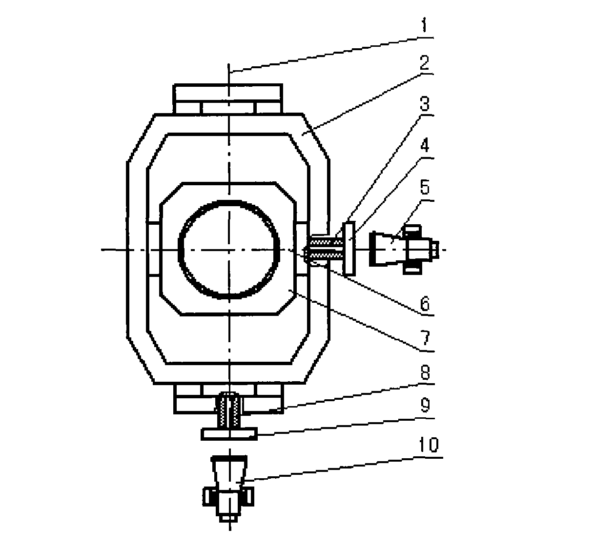
[0018] The present invention detects the method for the perpendicularity error of the longitude and latitude axes of the horizontal telescope, such as image 3 As shown, a plane reflector 4 is installed on the latitude axis 3 axis head of the horizontal telescope to be measured, a theodolite 5 is correspondingly placed outside the plane reflector 4, and the installation angle of the plane reflector 4 and the pendulum of theodolite 5 are adjusted. Place the position so that the optical axis of the theodolite 5 coincides with the axis of rotation 6 of the latitudinal axis; another plane reflector 9 is installed on the warp axis 8 axis head of the horizontal telescope to be measured, and another plane reflector 9 is correspondingly placed outside the plane reflector 9 Theodolite 10, adjust the installation angle of plane reflector 9 and the placement position of theodolite 1...


PUM


Abstract

The invention relates to an optical detection method of the verticality error of a longitudinal axis and a latitudinal axis of a horizontal type telescope, comprising the following steps: respectivelyinstalling an optical planar mirrors on axis heads of the longitudinal axis and the latitudinal axis of the horizontal type telescope; also correspondingly installing a theodolites on the outer sideof each optical planar mirror, and enabling optical axes of the two theodolites to respectively coincide with turning axes of the longitudinal axis and the latitudinal axis of the horizontal type telescope; rotating azimuth axes and pitch axes of the two theodolites, enabling the optical axes of the two theodolites to be aligned, and recording rotating azimuth angles (A1 and A2) of the two theodolites so that the verticality error of the longitudinal axis and the latitudinal axis of the horizontal type telescope is that delta=90 DEG-(A1+A2). The detection method has simple principle, is easy to operate compared with a star comparison method, does not need to know the position of a fixed star, is not limited by weather and fields, does not need to carry out complicated mathematical calculation and is easy to realize.

Description

technical field [0001] The invention relates to a method for detecting the verticality error of the longitude and latitude axes of a horizontal telescope. Background technique [0002] Horizontal telescopes are characterized by two mutually perpendicular mechanical axes parallel to the horizontal plane. These two mechanical axis systems are called warp axis and weft axis respectively. According to the arrangement of the optical system, the spatial positions of the warp axis and the latitude axis are divided into two types, that is, the space is orthogonal and the vertical disjoint. Due to processing errors and assembly errors, the two axes are often not perpendicular to cause pointing errors, such as figure 1 As shown, let the perpendicularity error between the latitude axis and the warp axis be δ, θ X , θ Y represent the rotation angles of the warp and latitude axes, respectively. Since the warp axis is not perpendicular to the weft axis, the visual axis rotates along ...

Claims


Application Information

Patent Timeline
IPC IPC(8): G01B11/26
Inventor 王志宋云夺王志臣
Owner CHANGCHUN INST OF OPTICS FINE MECHANICS & PHYSICS CHINESE ACAD OF SCI
Why Eureka
Try Eureka