
Method for manufacturing cold-finished seamless steel pipe for integrally molded drive shaft

A technology of seamless steel pipe and manufacturing method, which is applied in the directions of manufacturing tools, metal processing equipment, shafts, etc., can solve the problems of increasing the wrinkle depth on the inner surface of the pipe, etc.

Active Publication Date: 2012-01-04
NIPPON STEEL CORP
View PDF6 Cites 1 Cited by
  • Summary
  • Abstract
  • Description
  • Claims
  • Application Information

AI Technical Summary

Problems solved by technology

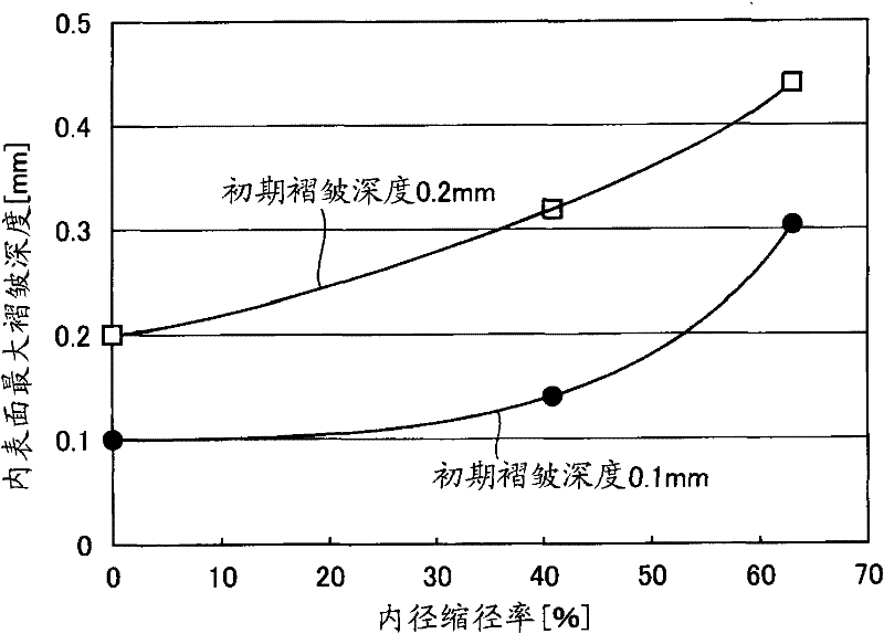
At this time, in the case of manufacturing an integrally formed drive shaft, the cold-worked ends are subjected to diameter reduction processing to increase the thickness of the walls. The fold depth of the

Method used


Image

  • Method for manufacturing cold-finished seamless steel pipe for integrally molded drive shaft
  • Method for manufacturing cold-finished seamless steel pipe for integrally molded drive shaft
  • Method for manufacturing cold-finished seamless steel pipe for integrally molded drive shaft

Examples


Embodiment 1

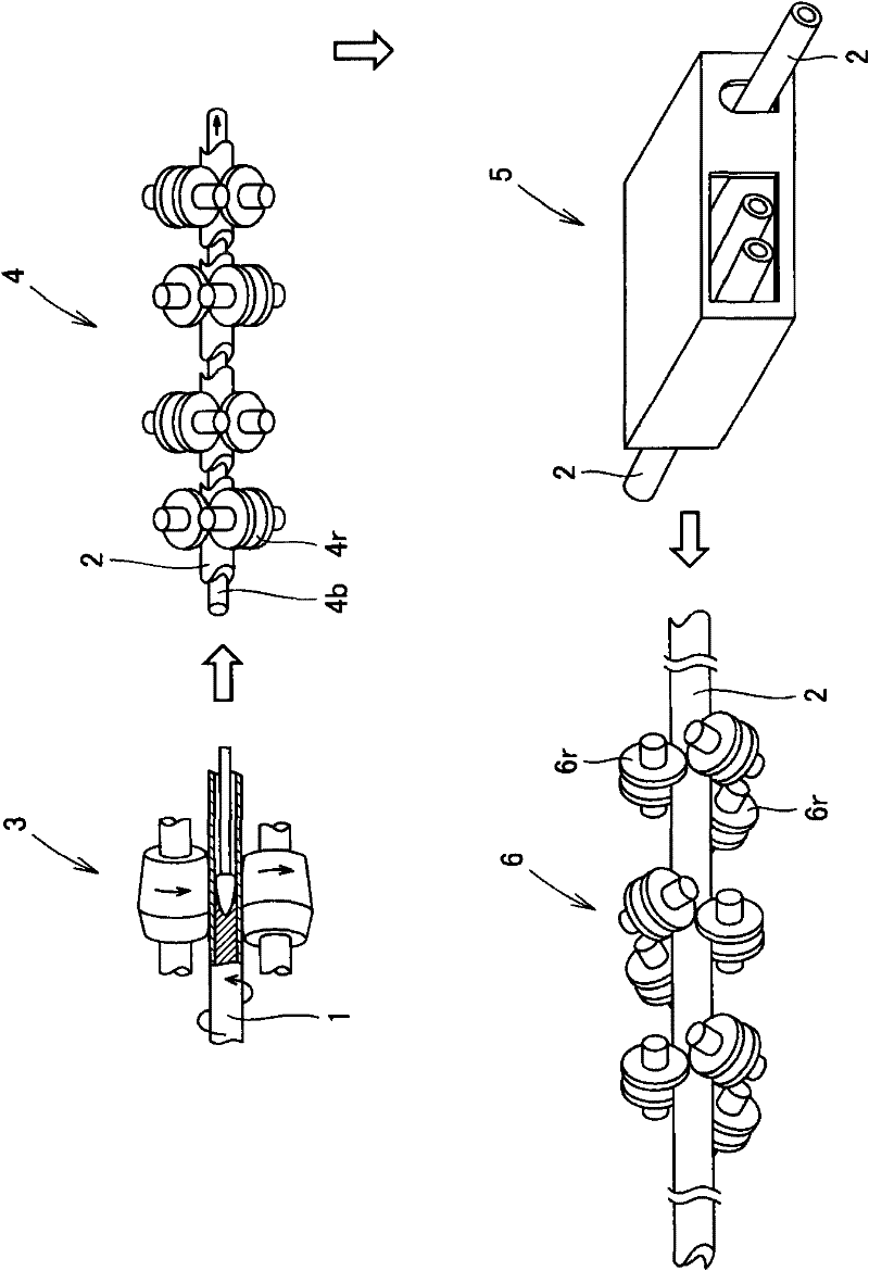
[0131] In Examples, steel slabs having chemical compositions shown in Table 1 were used. Then, as shown in the column of thermal processing pipe making in Table 2, the piercing and rolling are carried out by ordinary Mannesmann mandrel mill processing, and the pass shape (pass shape) of the 3-roll stretching and shrinking mill is changed. Roll minimum flange contact angle β min ), to manufacture cold-drawn tube blanks with an outer diameter of 45.0 mm and a wall thickness of 7.0 to 7.4 mm.

[0132] [Table 1]

[0133]

[0134] At this time, the minimum wall thickness in the circumferential direction of the pipe and the depth of the generated inner surface wrinkles were measured. The column of hot-worked tube making in Table 2 also shows the processing conditions (except the roll conditions of the stretching mill) and the measurement results of the minimum wall thickness and inner surface wrinkle depth in the hot-worked tube-making process at this time.

[0135] Cold draw...

Embodiment 2

[0150] Using the sample materials A to I subjected to diameter reduction in Example 1, a torsional fatigue test was implemented. As above Figure 4 As shown, for the sample material subjected to diameter reduction processing, the central part of the length of the sample was cut off by 3.5 mm from the outer diameter after cold drawing (to reduce the wall thickness by 1.75 mm), and a parallel part with a length of 150 mm was formed. This part forms a spline, and serves as a sample for simulating a splined portion of an integrally formed drive shaft.

[0151] Figure 8 It is a sectional view showing the splined shape of the sample subjected to the torsional fatigue test used in Example 2. The number of teeth of the spline processing part is slightly different depending on the outer diameter after the above-mentioned outer diameter cutting, but within the range of 25 to 31, the depth of the recess is 0.98mm, and the radius of curvature of the bottom of the recess is 0.4mm. The ...


PUM

PropertyMeasurementUnit
depthaaaaaaaaaa

Abstract

Provided is a cold-finished seamless steel pipe for an integrally molded drive shaft, which is obtained by cold-extracting a material pipe hot-rolled by the Mannesmann piercing method. In order to retain the maximum inner face wrinkle depth of 0.1 mm or less of the seamless steel pipe for the drive shaft and the maximum wrinkle depth of 0.20 mm or less of the inner face at the internal diameter reduction ratio of 30 % or more in the radially reduced portion, the material used is the steel of the kind having specific chemical compositions. This steel material is subjected to a piercing-rollingtreatment by the Mannesmann method, and is adjusted in the hole molding shape in the routine rolling after drawing-rolled, and then adjusted in the thickness treatment in the later cold-extraction. As a result, the seamless steel pipe can retain excellent torsional fatigue characteristics as the integrally molded automotive drive shaft having radially reduced portions at its two end portions, so that it can be used as a hollow member optimum for weight reduction and quietness. As a result, the automotive drive shaft can be efficiently manufactured.

Description

technical field [0001] The present invention relates to a cold-worked seamless steel pipe for a drive shaft, a drive shaft using the seamless steel pipe, and a method for manufacturing a cold-worked seamless steel pipe for a drive shaft. A cold-worked seamless steel pipe used as a hollow member that is light in weight, optimal in quietness, and excellent in torsional fatigue characteristics, a method for efficiently manufacturing the seamless steel pipe, and a drive shaft manufactured using the cold-worked seamless steel pipe. Background technique [0002] In recent years, the need to protect the global environment has been increasing, and in the field of the automobile industry, it is also required to reduce the weight of automobile bodies and further improve the effect of energy saving. Therefore, from the viewpoint of reducing the weight of the vehicle body, attempts have been made to replace solid members with hollow members for automobile parts, and hollow members made ...

Claims


Application Information

Patent Timeline
Patent Type & Authority Patents(China)
IPC IPC(8): B21B17/14C22C38/58C21D9/08C22C38/00B21B23/00B21C37/15C22C38/32
CPCB21B23/00C22C38/06B21B17/04F16C3/02C22C38/28B21B27/024C22C38/04C21D8/105C21D9/08B21B19/04B21B17/14C22C38/32
Inventor 山本忠之
Owner NIPPON STEEL CORP
Learn More