Electric main shaft of digital control machine tool

A technology of CNC machine tools and electric spindles, applied in the direction of electromechanical devices, mechanical energy control, electrical components, etc., can solve the problems of unreplaceable bearings, spindle damage, unfavorable precision machining, etc., to reduce manufacturing and use costs, facilitate assembly and disassembly, Facilitate the effect of precision machining

Inactive Publication Date: 2010-02-24
重庆九源机械有限公司
View PDF1 Cites 7 Cited by
  • Summary
  • Abstract
  • Description
  • Claims
  • Application Information

AI Technical Summary

Problems solved by technology

[0002] At present, common CNC machine tools on the market include a spindle and a motor. The motor transmits the power of the motor to the spindle through a belt drive or a gear drive to make the spindle rotate. This structure has the following problems: First, the vibration is large, which is not conducive to precision machining; It is the large loss in the process of power transmission, so that the maximum speed of the main shaft is generally 2000 rpm-3000 rpm; the third is that the transmission mechanism is complex and the cost is relatively high
In this patent, the rotor is directly fixed on the main shaft, and the interference fit is used between them. When the main shaft needs to be disassembled for maintenance, the disassembly of the main shaft will be damaged. At the same time, the bearing cannot be replaced due to the interference fit. , when the bearing of the main shaft is damaged, the main shaft can only be scrapped

Method used


Image

  • Electric main shaft of digital control machine tool

Examples


Embodiment

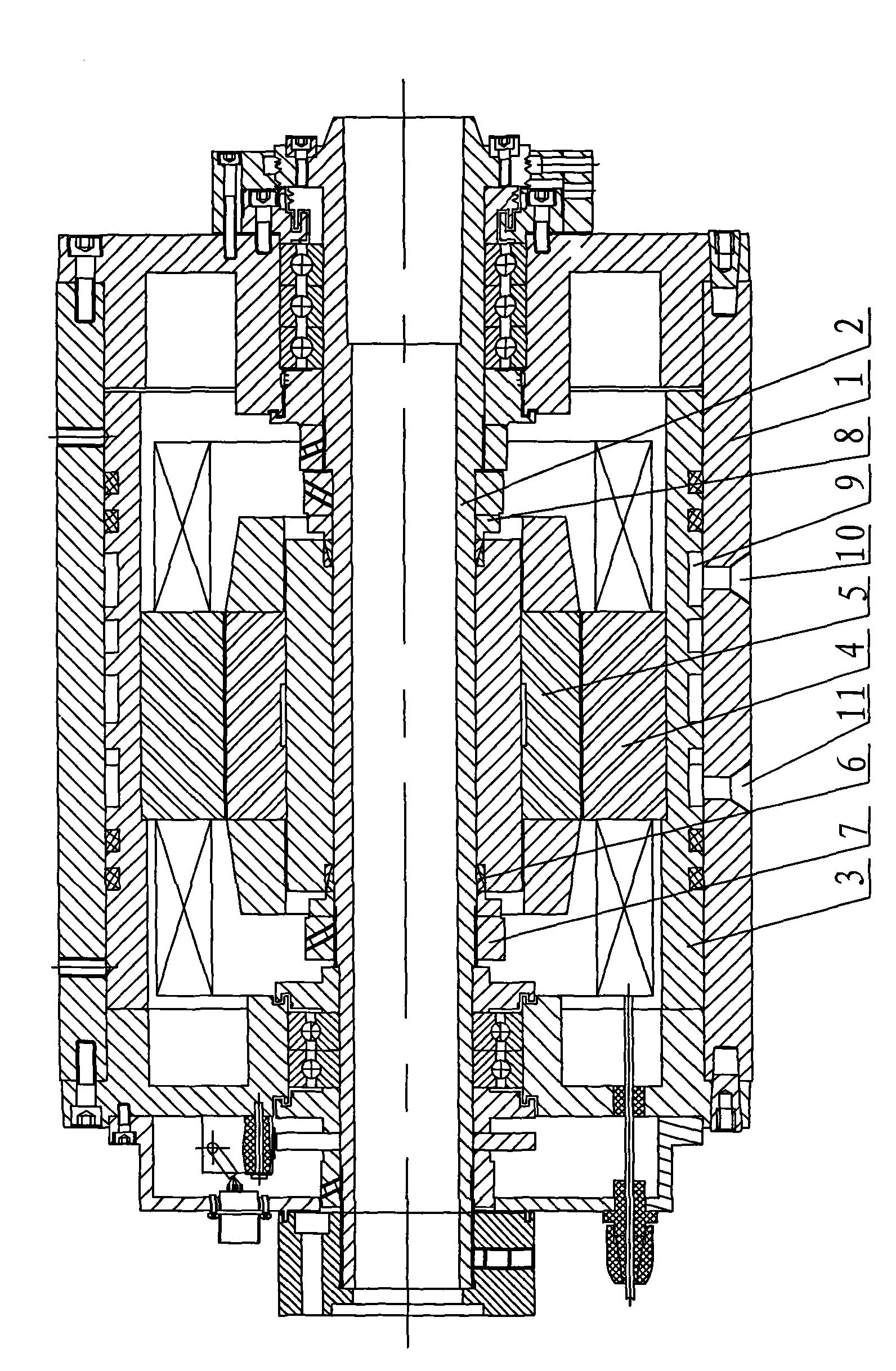
[0011] Example: such as figure 1 As shown, an electric spindle of a CNC machine tool includes a spindle 2 and a motor arranged in a box body 1. The motor includes a housing 3 and a rotor 4. The rotor 4 is inserted into the spindle 2 and is located in the middle of the spindle 1. The rotor 4 passes through the expansion The tightening device is connected with the main shaft 2.

[0012] The tensioning device in this example includes a spacer 5 arranged between the rotor 4 and the main shaft 2, and an expansion sleeve 6 is arranged at both ends of the spacer 5, and the above-mentioned expansion sleeve 6 is pressed into the space between the spacer 5 and the main shaft 2 In the gap, a lock nut 7 is arranged on the outside of the expansion sleeve 6, and the above lock nut 7 compresses the expansion sleeve 6 through the pressure spacer 8.

[0013] A circulating water channel 9 is arranged in the casing 3 , and the above-mentioned circulating water channel 9 is arranged laterally in...


PUM


Abstract

The invention discloses an electric main shaft of a digital control machine tool, comprising a main shaft (2) which is arranged in a box body (1) and an electromotor, wherein the electromotor comprises a casing (3) and a rotor (4); and the rotor (4) is sheathed in the main shaft (2) and is located in the middle part of the main shaft (1). The invention is characterized in that the rotor (4) is connected with the main shaft (2) through a swelling device. The invention has the advantages of compact mechanism, small vibratility and high rotate speed.

Description

technical field [0001] The invention relates to an electric spindle of a machine tool, in particular to an electric spindle of a numerical control machine tool. Background technique [0002] At present, common CNC machine tools on the market include a main shaft and a motor. The motor transmits the power of the motor to the main shaft through a belt drive or a gear drive to make the main shaft rotate. This structure has the following problems: First, it has a large vibration, which is not conducive to precision machining; It is that the loss in the power transmission process is relatively large, so that the maximum speed of the main shaft is generally 2000 rpm-3000 rpm; the third is that the transmission mechanism is complicated and the cost is relatively high. In order to solve the above-mentioned problems, many manufacturers directly connect the motor to the main shaft. For example, CN201076995Y discloses a utility model patent entitled "Electric Spindle Mechanism of Machi...

Claims


Application Information

Patent Timeline
IPC IPC(8): B23Q5/10H02K7/10H02K9/19
Inventor 曹伯云
Owner 重庆九源机械有限公司
Why Eureka
Try Eureka