
Optical fibre complete exchange equipment and method

A full-switching, optical fiber technology, applied in the network field, can solve the problems of loss, system cost increase, output optical signal strength attenuation, etc., and achieve the effect of reasonable number, equipment cost saving, and strong practicability.

Inactive Publication Date: 2010-02-24
NINGBO YINGMING ELECTRIC TECH
View PDF0 Cites 15 Cited by
  • Summary
  • Abstract
  • Description
  • Claims
  • Application Information

AI Technical Summary

Problems solved by technology

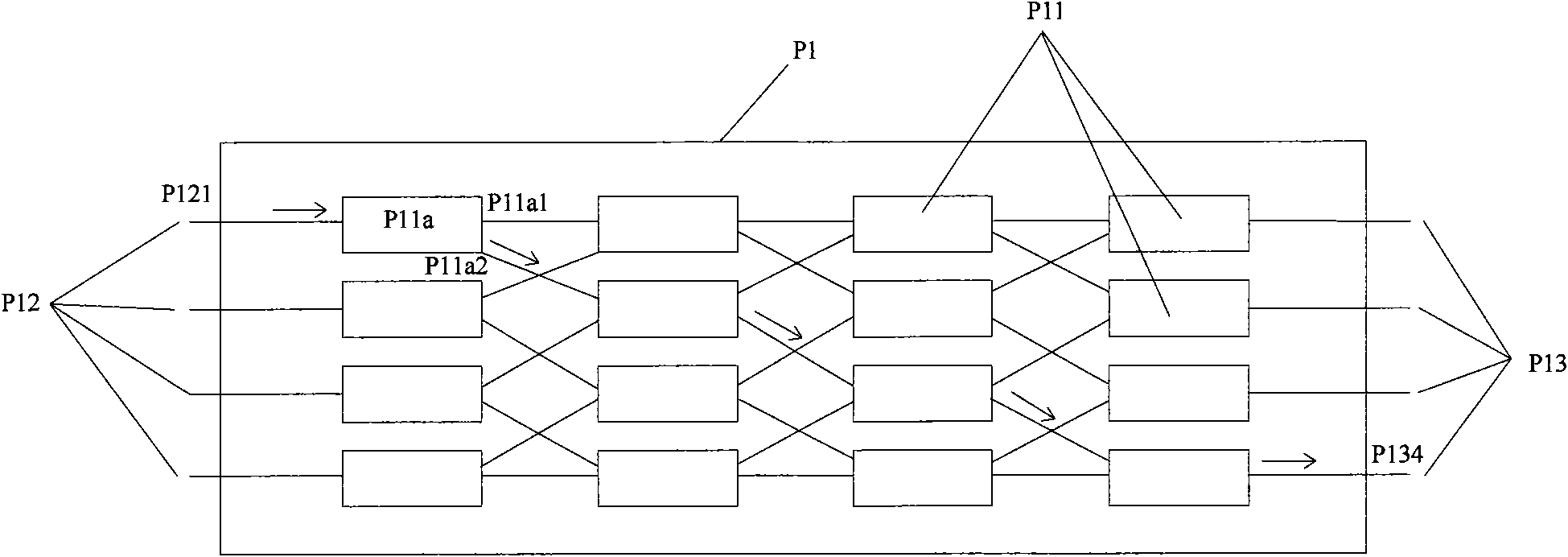
[0005] However, since the number of optical waveguide coupling regions P11 inside the optical switch P1 is related to the maximum number of input fibers and output fibers that the optical switch P1 can access, that is, when The increase of the number of input optical fibers or output optical fibers must increase the number of optical waveguide coupling areas inside the optical switch, and the light input from the input optical fiber will produce a certain degree of loss every time it passes through an optical waveguide coupling area P11, so in the input optical fiber Or when the number of output optical fibers is large, the light must pass through a large number of optical waveguide coupling regions before it can be output from the output optical fiber, so that the output optical signal intensity attenuates seriously; on the other hand, due to the structure and working principle of the optical switch Limitation, the optical switch can only realize the exchange between any input fiber and any output fiber, and cannot realize the exchange between two input fibers, that is, it cannot realize all the fibers connected to the optical switch (including Arbitrary switching between input fiber and output fiber), that is, "full switching" cannot be achieved
[0006] In addition, in many practical applications, although it is necessary to enable any two access fibers to be switched, that is, to achieve full switching, it does not mean that all access fibers must be switched in pairs at the same time. There are 16 optical fibers. If two-two switching is performed at the same time, a total of 8 pairs of connected optical fibers are switched at the same time. However, for the actual network environment, the task load is always small, and two-two switching is performed every moment. There may only be up to 4 pairs
As the number of optical fibers that the system can realize two-two switching at the same time will increase the system cost, how to further save the system cost according to the actual situation while realizing full switching has become a problem that people are more concerned about.

Method used


Image

  • Optical fibre complete exchange equipment and method
  • Optical fibre complete exchange equipment and method
  • Optical fibre complete exchange equipment and method

Examples


Embodiment 1

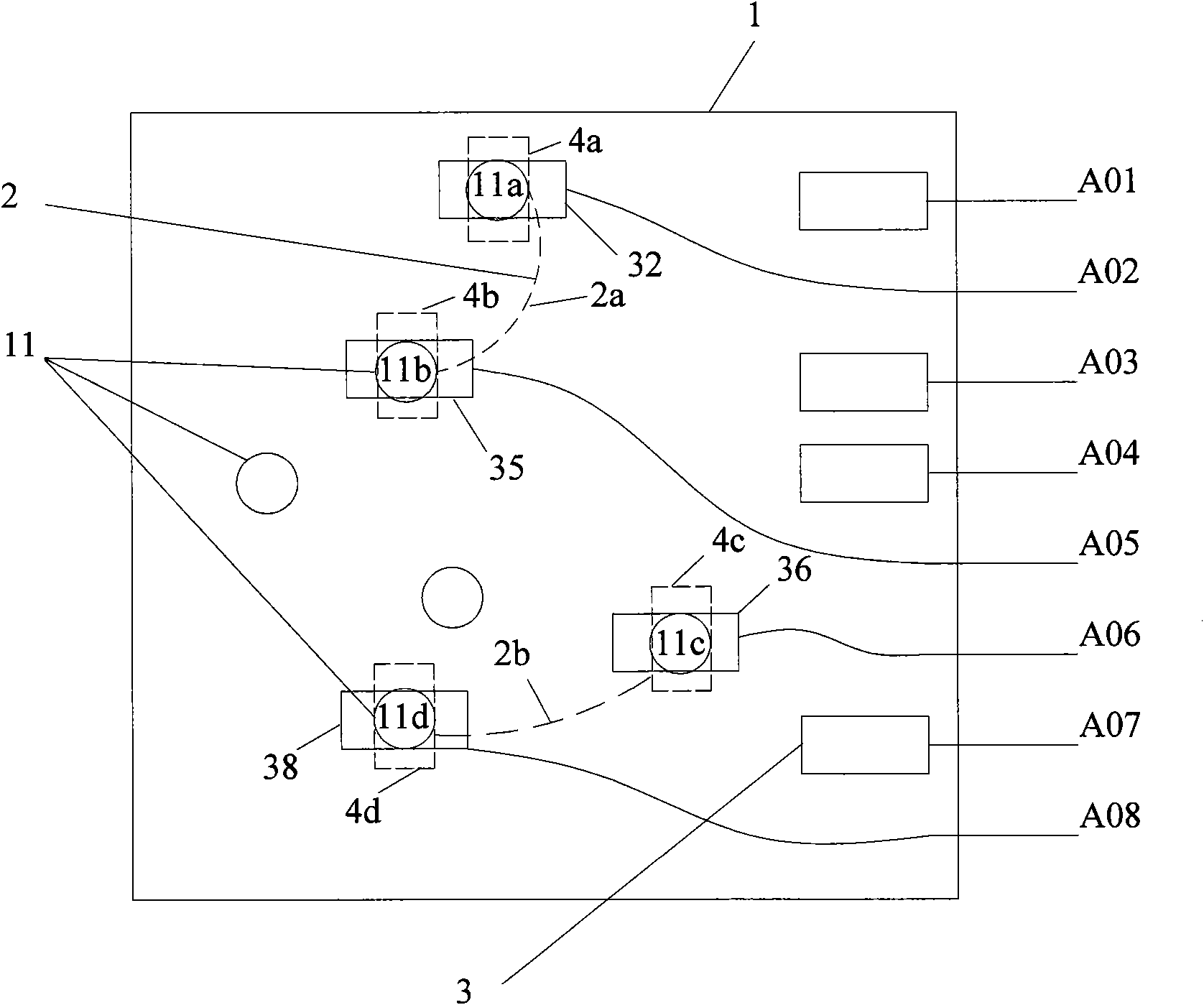
[0028] Embodiment 1 of the present invention provides an optical fiber full switching device, figure 2 shows a schematic plan view of the optical fiber full switching device provided in the first embodiment, as shown in figure 2 As shown, the device includes: an exchange plate 1, a plurality of exchange holes 11 are formed on the exchange plate 1, figure 2 Only schematically draw 6 exchange holes in the figure, one side of the exchange hole 11 is used to insert the line fiber optic connector, and the other side is used to insert the line fiber optic connector 3, in figure 1 Among them, the side for inserting the line fiber optic connector is the lower side of the switch board, and the side for inserting the line fiber optic connector 3 is the upper side of the switch board. One end of each external line fiber is fixed in a corresponding line fiber connector 3, and each line fiber connector 3 only fixes one external line fiber, such as figure 2 As shown, in this embodimen...

Embodiment 2

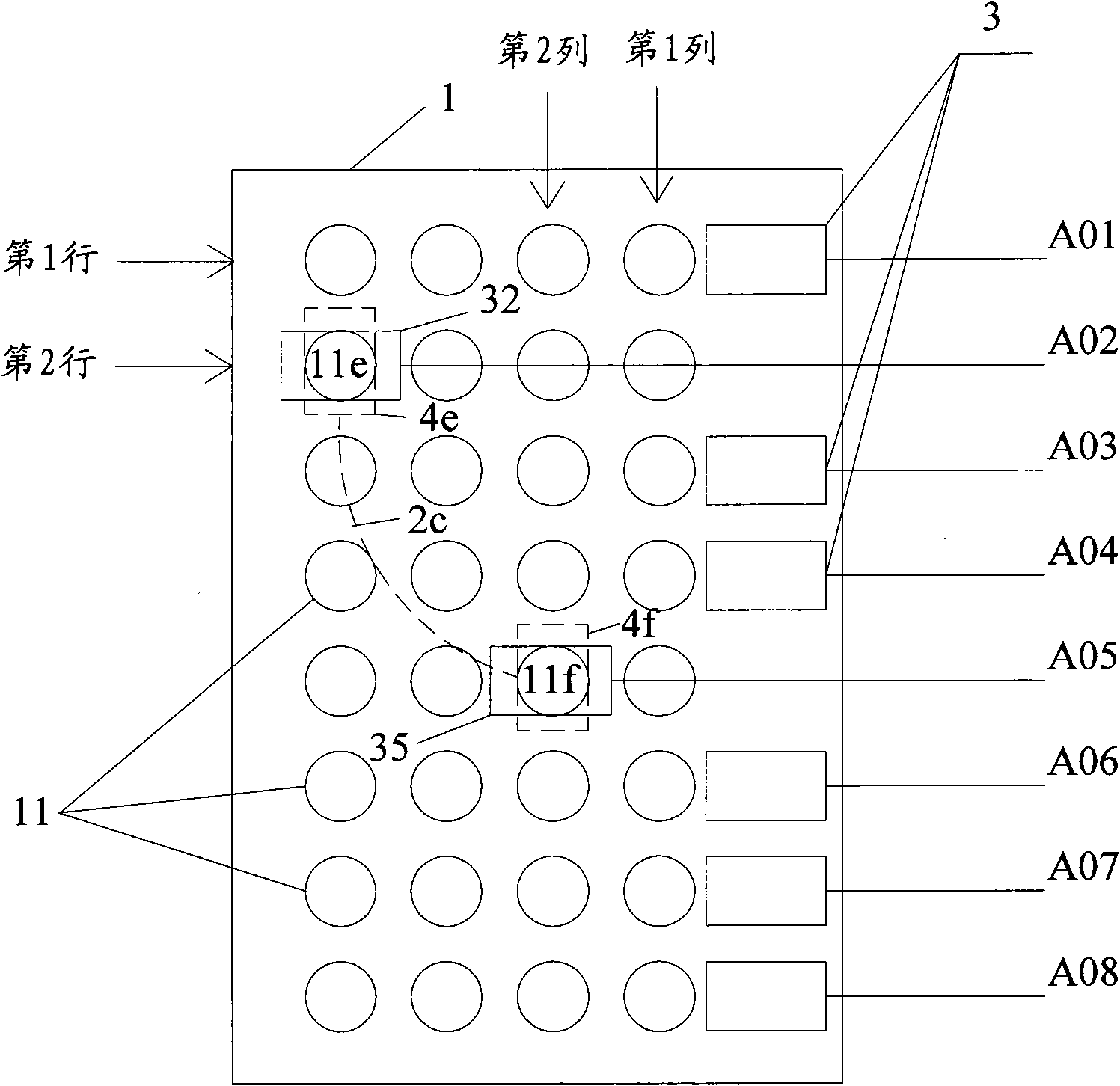
[0039] This embodiment proposes a specific implementation scheme based on the optical fiber full switching device proposed in Embodiment 1, such as image 3 As shown, in this embodiment, the exchange holes 11 on the exchange plate 1 are arranged in a uniform rectangular array. Such a design can make the positioning of the driving device drive the linker more convenient during the movement process, because the identification of the position of each exchange hole in the system will become very simple.

[0040] In addition, in order to further improve the efficiency of finding free switching holes, the switching holes arranged in a rectangular array are divided. Preferably, each external line fiber corresponds to a row of switching holes. It should be noted that the concepts of row and column are not absolute. Yes, just as the selection of the coordinate system is not absolute, when viewed from another angle, the original "row" can also be regarded as a new "column". Therefore, ...

Embodiment 3

[0049] Compared with Embodiment 1, the optical fiber full switching device provided in this embodiment not only divides the rows of switching holes, but also divides the columns of switching holes. Such as Figure 4 As shown, the switching holes 11 on the switching board 1 in the optical fiber full switching device provided by this embodiment are still arranged in a uniform rectangular array, and one side of the switching holes 11 is used for inserting a cable fiber optic connector, and the other side is used for inserting Line fiber optic connector. Preferably, each external line fiber corresponds to a row of switching holes, and each rope fiber corresponds to a row of switching holes, and the line fiber connector fixing one end of each external line fiber can only be restricted to move on the row corresponding to the external line fiber, And can only be inserted into the exchange hole in this row, and a pair of rope fiber optic connectors that fix the two ends of a rope fib...


PUM


Abstract

The invention provides optical fibre complete exchange equipment and an optical fibre complete exchange method, wherein the equipment comprises an exchange plate, a search device and a driving device,wherein a plurality of exchange holes are formed on the exchange plate, both ends of each cord circuit optical fibre are respectively fixed in a pair of cord circuit optical fibre linkers, and one end of each outside line optical fibre is respectively fixed in a line optical fibre linker; the number of the cord circuit optical fibres is smaller than one half of the number of the outside line optical fibres; the search device is used for searching a pair of exchange holes which is idle at one side and is arranged on the exchange plate as well as used for inserting the line optical fibre linkerand used as a pair of target exchange holes; and the driving device is used for driving and fixing the line optical fibre linkers which need to be exchanged and arranged at the end parts of any two outside line optical fibres to respectively move to the target exchange holes and to be inserted into the target exchange holes, and is also used for respectively moving a pair of unoccupied cord circuit optical fibre linkers to the target exchange holes and to be inserted into the target exchange holes. The embodiment of the invention can realize the complete exchange among outside line optical fibres, optical signals have smaller attenuation, and the cost can be effectively saved.

Description

technical field [0001] The invention relates to the field of network technology, in particular to an optical fiber full switching device and method. Background technique [0002] In the optical fiber network, which is the basic bearer network for communication transmission, the optical fiber switching equipment is the key equipment to complete the switching between optical fibers. [0003] At present, for the switching equipment in the optical fiber network, it is usually necessary to manually go to the site to perform fiber jumping operations to realize the switching between different optical fibers. In daily work, such manual operations are huge and time-consuming. become a matter of great concern to people. [0004] In order to achieve remote control, there is a solution in the prior art to use an optical switch as an optical fiber switching device. One side of the optical switch is connected to several optical fibers for input, and the other side is connected to several...

Claims


Application Information

Patent Timeline
Patent Type & Authority Applications(China)
IPC IPC(8): G02B6/38
Inventor 范骏行戎家铨
Owner NINGBO YINGMING ELECTRIC TECH
Learn More