Device for dry etching

A technology of dry etching and etching gas, applied in the manufacture of electrical components, circuits, semiconductor/solid-state devices, etc., can solve problems such as low production efficiency, and achieve the effect of improving production efficiency and production speed

Active Publication Date: 2010-02-24
K TRONICS (SUZHOU) TECH CO LTD +1
View PDF0 Cites 7 Cited by
  • Summary
  • Abstract
  • Description
  • Claims
  • Application Information

AI Technical Summary

Problems solved by technology

[0009] The object of the present invention is to provide a dry etching device, which effectively solves the problem of etching materials such as Al, a-Si, SiNx or Mo with a dry etching device. The defect of low production efficiency makes it possible to etch materials such as a-Si, SiNx or Mo quickly with a dry etching device not only uniformly

Method used


Image

  • Device for dry etching
  • Device for dry etching
  • Device for dry etching

Examples


Embodiment 1

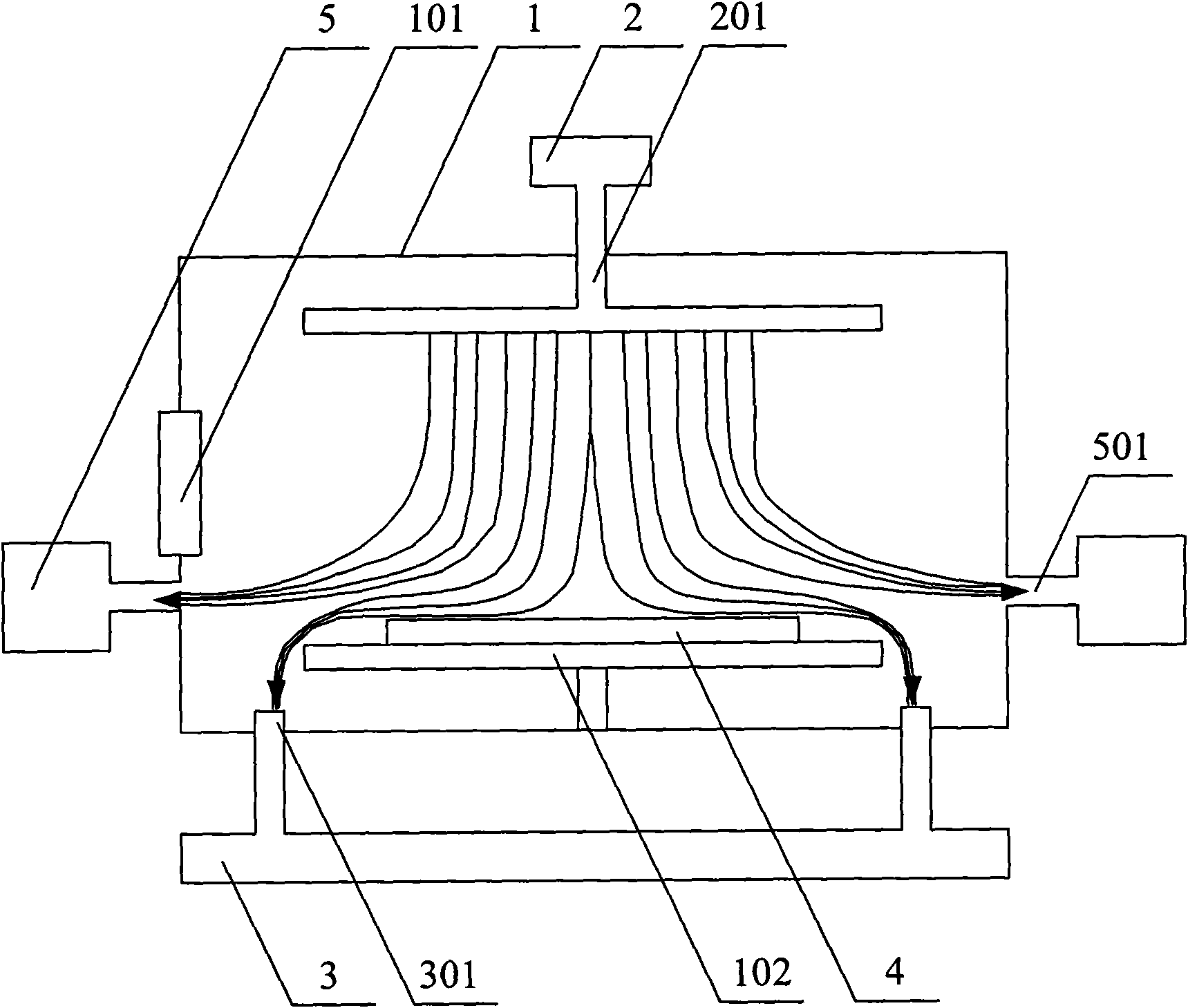
[0033] image 3 It is a schematic diagram of Embodiment 1 of the present invention. Such as image 3 As shown, the dry etching device includes: a chamber 1 for etching; a chamber door 101 arranged on the side of the chamber 1 for transferring the substrate; a base 102 erected at the bottom of the chamber 1 for placing the substrate 4; An inlet 2 for blowing etching gas into the chamber 1; an inlet pipe 201 communicating the inlet 2 with the top of the chamber 1, so that the etching gas is blown in from the top of the chamber 1; The aspirator 3 for extracting the etching gas in the chamber 1; the aspirator 301 communicating the aspirator 3 with the bottom of the chamber 1; The etching gas in the chamber 1 is an auxiliary pumping device for controlling the contact density of the etching gas and the substrate 4, and the auxiliary pumping device is composed of an auxiliary pumping device 5 and an auxiliary pumping pipe 501 capable of controlling the pumping volume. Specifically...

Embodiment 2

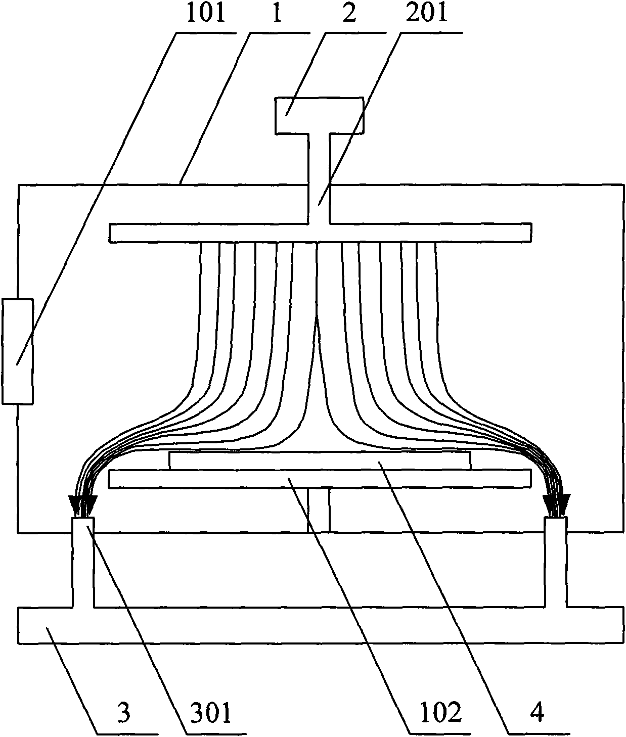
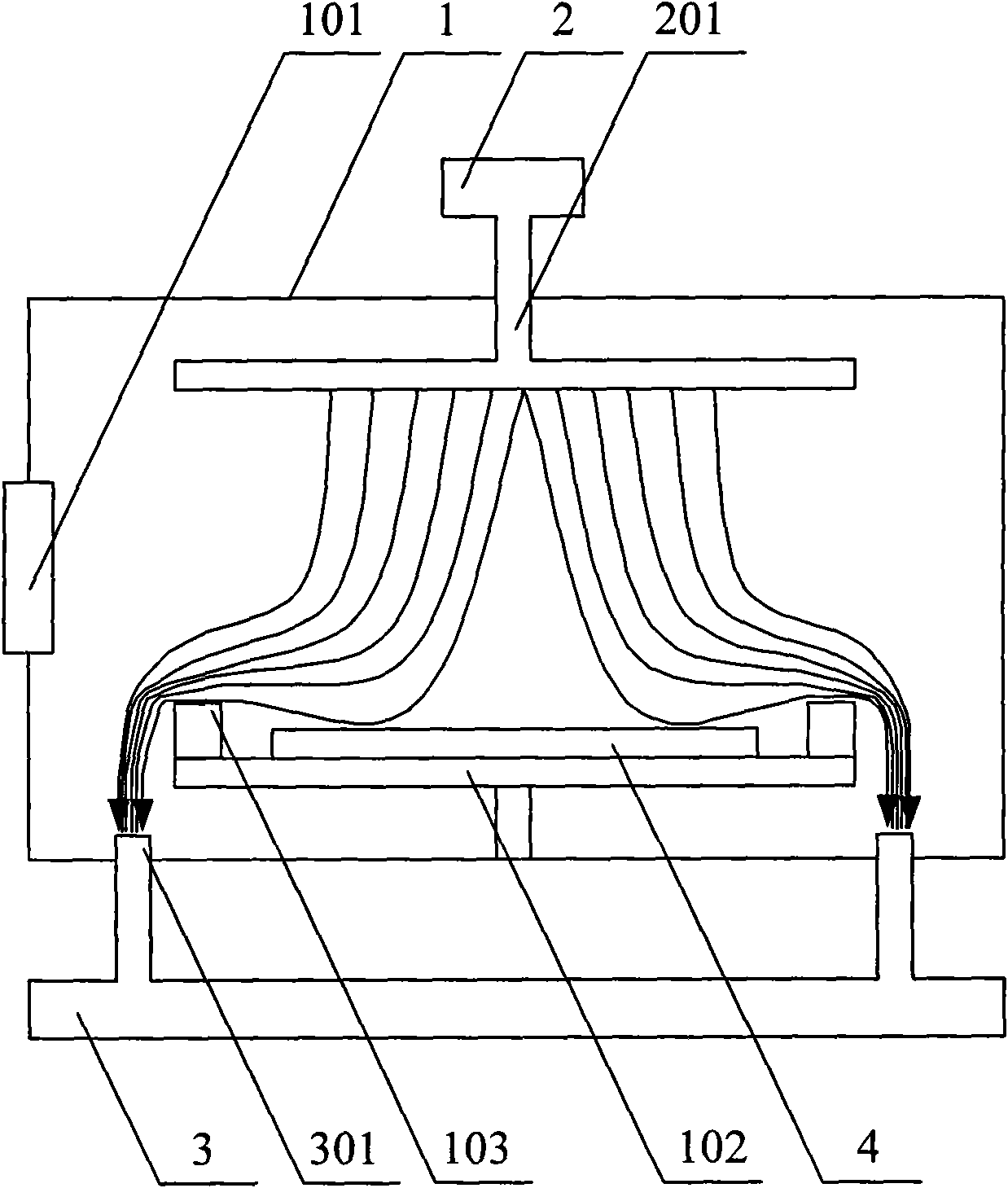
[0040] Figure 4 It is a schematic diagram of Embodiment 2 of the present invention. Such as Figure 4 As shown, the dry etching device includes: a chamber 1 for etching; a chamber door 101 arranged on the side of the chamber 1 for transferring the substrate; a base 102 erected at the bottom of the chamber 1 for placing the substrate 4; An inlet 2 for blowing etching gas into the chamber 1; an inlet pipe 201 communicating the inlet 2 with the top of the chamber 1, so that the etching gas is blown in from the top of the chamber 1; The aspirator 3 for extracting the etching gas in the chamber 1; the aspirator 301 communicating the aspirator 3 with the bottom of the chamber 1; The etching gas in the chamber 1 is used to control the contact density of the etching gas and the substrate 4. The auxiliary pumping equipment is composed of an auxiliary pumping pipe 501 and a valve 6 for controlling the pumping volume of the auxiliary pumping pipe. The auxiliary pumping pipe 501 One end...

Embodiment 3

[0046] Figure 5 It is a schematic diagram of Embodiment 3 of the present invention. Such as Figure 5 As shown, the dry etching device includes: a chamber 1; a chamber door 101 arranged on the side of the chamber 1 for transferring substrates; a base 102 erected at the bottom of the chamber 1 for placing the substrate 4; Intaker 2 for blowing etching gas into 1; Inlet pipe 201 connecting the inlet 2 and the top of chamber 1, so that etching gas is blown in from the top of chamber 1; used to extract etching from chamber 1 The air extractor 3 of the gas; the exhaust pipe connecting the air extractor 3 and the bottom of the chamber 1; the upper casing 7 and the lower casing 8 which can be tightly nested with each other are also arranged in the chamber 1, and the lower casing The bottom of 8 is provided with a suction port, and the side of the lower shell 8 is provided with an auxiliary suction port 9, the horizontal position of the auxiliary suction port 9 is higher than the h...


PUM


Abstract

The invention relates to a device for dry etching, which comprises a cavity, a base platform erected at the bottom of the cavity, a gas intake device and a gas extractor. The device also comprises atleast one assistant gas extracting device which is arranged on the lateral surface of the cavity and is used for controlling the contact density of an etching gas and a substrate by pumping the etching gas in the cavity out from the upper part of the base platform. When the device for the dry etching etches the materials of a-Si, SiNx or Mo and the like, the assistant gas extracting device is turned off; when the device etches the materials of Al and the like which are sensitive to the etching gas, the assistant gas extracting device is turned on; besides, the device controls the contact density of the etching gas and the substrate by pumping the etching gas in the cavity out from the upper part of the base platform, thus a gas adjusting seat is not needed to be assembled or disassembled when one device for the dry etching is used for etching various materials, and the production efficiency and the production speed are effectively improved.

Description

technical field [0001] The invention relates to a dry etching device, in particular to a dry etching device capable of controlling the flow direction of etching gas in a chamber. Background technique [0002] The etching process is an important step in the process of manufacturing a Thin Firm Transistor Liquid Crystal Display (TFT-LCD for short) array substrate. The etching process is divided into a dry etching process and a wet etching process according to the physical state of the etchant, that is, the dry etching process is an etching process using an etching gas, and the wet etching process is an etching process using an etching liquid. [0003] figure 1 It is a schematic diagram of an existing dry etching device, such as figure 1 As shown, the dry etching device includes: a chamber 1 (chamber) for etching; a chamber door 101 arranged on the side of the chamber 1 for transferring substrates; Platform (stage) 102; The gas inlet 2 that is used for blowing etching gas in...

Claims


Application Information

Patent Timeline
Patent Type & Authority Applications(China)
IPC IPC(8): H01L21/00H01L21/02H01L21/306H01L21/311H01L21/3213C23F1/08
Inventor 刘圣烈崔承镇宋泳锡董敏
Owner K TRONICS (SUZHOU) TECH CO LTD
Why Eureka
Try Eureka