Key manufacturing technology of built-in type permanent magnet synchronous electric motor rotor

A technology of permanent magnet synchronization and manufacturing process, which is applied in the manufacture of stator/rotor bodies, etc., can solve the problems of difficult assembly of permanent magnets, achieve the effects of shortening the production cycle, improving the quality of lamination, and high first-time pass rate

Active Publication Date: 2010-02-24
SHANGHAI ELECTRICAL APPLIANCES RES INSTGROUP
View PDF2 Cites 24 Cited by
  • Summary
  • Abstract
  • Description
  • Claims
  • Application Information

AI Technical Summary

Problems solved by technology

[0005] The purpose of the present invention is to provide the key manufacturing process of the rotor of the built-in permanent magnet synchronous motor, which is used to solve the problem that the permanent magnet of the built-in permanent magnet synchronous motor is di

Method used


Image

  • Key manufacturing technology of built-in type permanent magnet synchronous electric motor rotor
  • Key manufacturing technology of built-in type permanent magnet synchronous electric motor rotor

Examples


Embodiment Construction

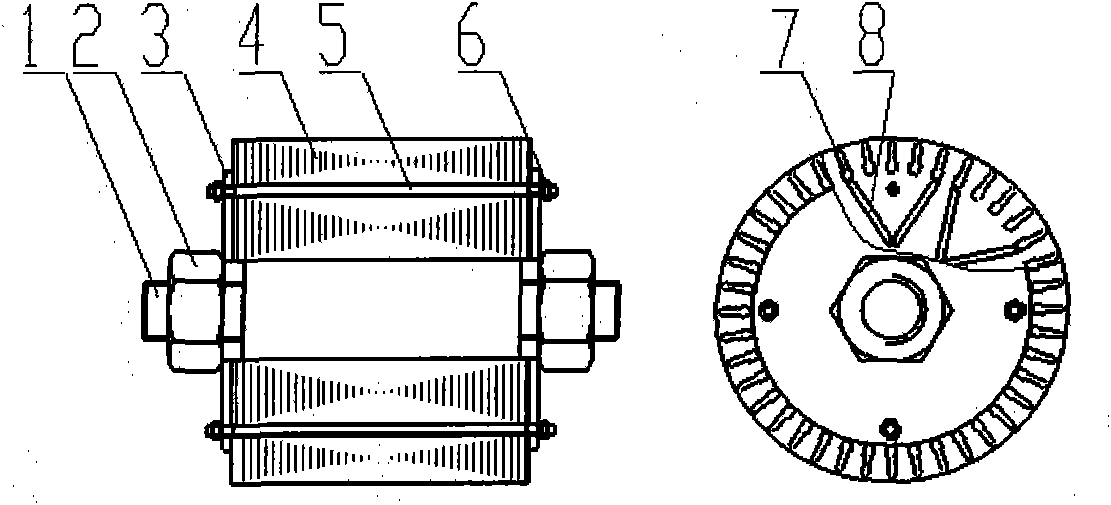
[0016] refer to figure 1 , which is a structural schematic diagram of the permanent magnet synchronous motor rotor of the present invention.

[0017] As shown in the figure, the parts are as dummy shaft 1, big nut 2, rotor baffle 3, rotor core 4, stud bolt 5, nut 6, rotor slot 7, permanent magnet slot 8.

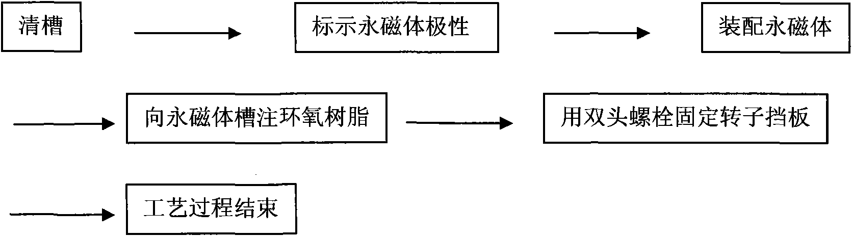
[0018] Using the shaft hole keyway for positioning, the positioning method has low precision, the quality of the rotor core cannot meet the precision requirements, the flatness of the permanent magnet groove cannot be guaranteed, and the quality of the core cannot meet the precision requirements. The usual solution is to manually grind the permanent magnet slots to increase the air gap on both sides of the permanent magnet slots so that the permanent magnets can be loaded into the rotor of the permanent magnet motor. However, this process wastes a lot of time and manpower and prolongs The production cycle of the motor and the processing cost of the motor are increased, and ...


PUM


Abstract

The invention relates to a key manufacturing technology of a built-in type permanent magnet synchronous electric motor rotor. An iron core overlying technology comprises the following steps: fixing adummy shaft, and sleeving the dummy shaft into a rotor baffle plate; sleeving arranged rotor sheets into the dummy shaft; inserting two stud bolts, and screwing nuts; then sequentially sleeving rotorsheets into the dummy shaft; installing the rotor baffle plate at the other side of the overlayed rotor sheet, and then fixing the rotor baffle plate; and overlying and firming the rotor sheets on a press machine. A permanent magnet assembling technology comprises the following steps: cleaning a permanent magnet groove, i.e. adding a groove cleaning technology, wherein a groove cleaning tool is asquare lead block, and the permanent magnet groove reaches a permanent magnet groove assembly requirement after being cleaned; marking the polarity of each permanent magnet; placing the permanent magnets into the permanent magnet groove of the rotor; pushing the permanent magnets to the bottom of the permanent magnet groove by a non-magnetic rigid round bar till the permanent magnet groove is filled with the permanent magnets; and pouring epoxy resin glue into the permanent magnet groove. The invention has simple and practical technology process and higher primary qualification rate of products and shortens the production period of the products.

Description

technical field [0001] The invention relates to a key manufacturing process of a rotor of a built-in permanent magnet synchronous motor, and belongs to the technical field of motors. Background technique [0002] In recent years, the asynchronous start permanent magnet synchronous motor has attracted wide attention from all aspects due to its excellent performance such as high efficiency and power factor. Many studies have been done on the mechanism and improving the operating efficiency and power factor of the motor. It is believed that the processing technology is crucial to the energy efficiency and quality of the permanent magnet motor, but there are few mature technologies. [0003] After patent retrieval, Chinese patent 01140086.2 discloses the composition of a synchronous motor rotor and a method for manufacturing a synchronous motor rotor. The synchronous motor rotor structure includes a main iron core and an auxiliary iron core, and the permanent magnet is tile-shap...

Claims


Application Information

Patent Timeline
IPC IPC(8): H02K15/03
Inventor 陈伟华姚丙雷张宝强徐全
Owner SHANGHAI ELECTRICAL APPLIANCES RES INSTGROUP
Why Eureka
Try Eureka