Canned linear motor armature and canned linear motor

An electromechanical and electromechanical technology, applied in electromechanical devices, electromechanical components, electrical components, etc., can solve the problems of increasing thermal time constant, increasing thermal resistance, and rising surface temperature of the shell, so as to eliminate the reduction of insulation resistance and reduce viscosity. Power, the effect of reducing temperature rise

Inactive Publication Date: 2010-02-24
YASKAWA DENKI KK
View PDF6 Cites 23 Cited by
  • Summary
  • Abstract
  • Description
  • Claims
  • Application Information

AI Technical Summary

Problems solved by technology

[0027] (1) Since water is used as a refrigerant, water seeps into the pores of the molded resin or the gap between the substrates, causing the insulation resistance of the armature winding to decrease or the insulation to be destroyed
[0028] (2) In order to avoid the problem of (1), when the molded resin between the armature winding and the refrigerant flow path is thickened, or a new insulating layer is installed, the thickness of the armature winding must be changed accordingly. As a result, the current for the specified thrust becomes larger, increasing the copper loss and even increasing the temperature rise of the armature winding wire and the shell surface
[0029] (3) In addition, since the insulating layer becom

Method used


Image

  • Canned linear motor armature and canned linear motor
  • Canned linear motor armature and canned linear motor
  • Canned linear motor armature and canned linear motor

Examples


Embodiment 1

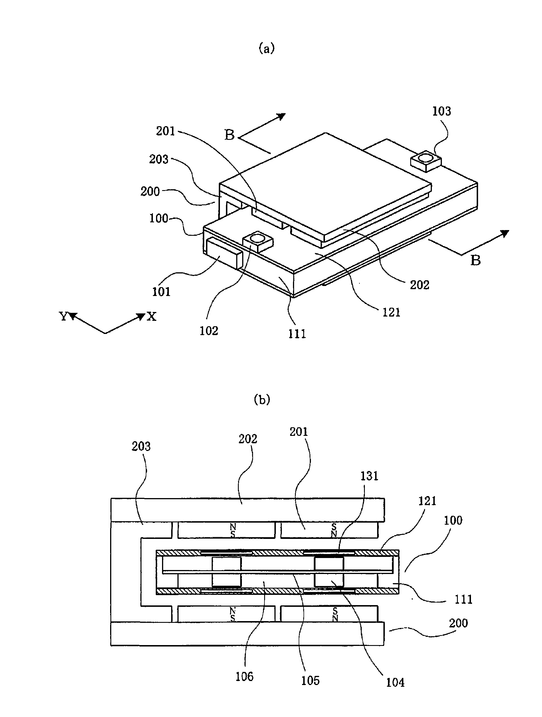
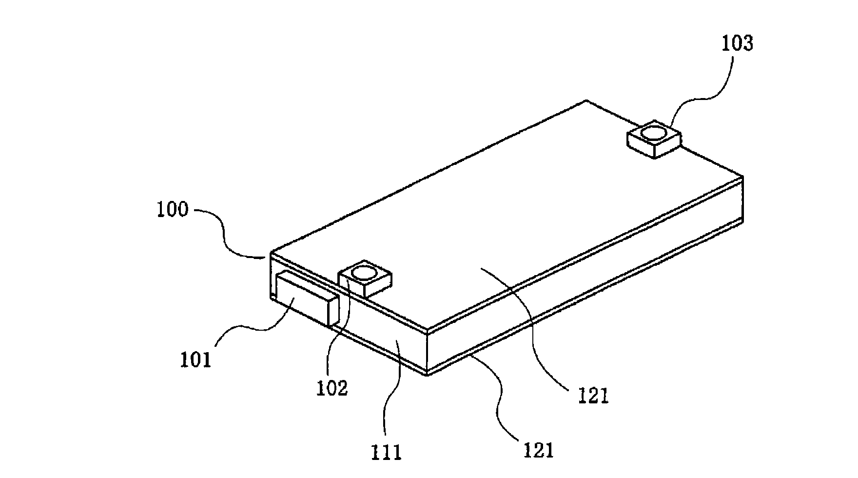
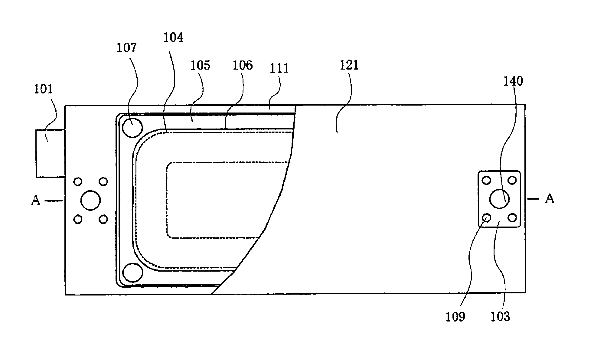
[0129] figure 1 It is a sealed linear motor common to the first to fifth embodiments of the present invention, (a) is an overall perspective view thereof, and (b) is a front sectional view along line B-B viewed from the X direction of (a). in addition, figure 2 It is a perspective view showing the armature of the sealed linear motor according to the first embodiment of the present invention, image 3 From figure 2 The top view of the armature viewed from above, in which a part of the case is cut away to clearly show the positional relationship between the armature coil and the substrate inside the armature, Figure 4 From figure 2 A top view of the armature viewed from above, in which a part of the shell is cut away to clearly show the positional relationship between the armature coil and the refrigerant flow path inside the armature, Figure 5 is along image 3 Side cutaway view of the armature along the line A-A. In addition, the same reference numerals are attache...

Embodiment 2

[0135] Next, a second embodiment of the present invention will be described.

[0136] Figure 6It is a plan view showing the armature viewed from the upper surface of the case of the second embodiment, in which a part of the case is cut away to clearly show the positional relationship between the armature winding and the refrigerant flow path inside the armature. The difference between the second embodiment and the first embodiment is that the refrigerant flow path 132 provided in the case 122 is formed in a meandering shape on the coil side surface of the armature winding 104 .

[0137] According to such a configuration, when the refrigerant flow path is formed in a serpentine shape, the heat transfer coefficient increases with the increase of the refrigerant flow rate, and the heat transfer area from the coil side of the armature winding to the shell increases. Therefore, compared with the first embodiment, the temperature rise of the armature winding can be further reduced...

Embodiment 3

[0139] Next, a third embodiment of the present invention will be described.

[0140] Figure 7 It is a plan view showing the armature viewed from the upper surface of the case of the third embodiment, in which a part of the case is cut away to clearly show the positional relationship between the armature winding and the refrigerant flow path inside the armature. The difference between the third embodiment and the second embodiment is that a long hole 150 is provided in the thick portion of the case 122 .

[0141] According to such a composition, as Figure 38 (b) shows the vortex 152 being refined. Thereby, viscous braking force can be reduced compared with the prior art, the first embodiment, and the second embodiment. Furthermore, since the long hole is provided without contacting the refrigerant flow path, no leakage of the refrigerant from the long hole occurs.


PUM

PropertyMeasurementUnit
Thermal conductivityaaaaaaaaaa

Abstract

A canned linear motor armature and a canned linear motor of water cooling type are provided. The insulation reliability of a canned linear motor armature is improved. The temperature rises of both the linear motor surface and the armature winding are reduced. Even if the coolant pressure increases, the can neither breaks nor deforms. The weight of the armature is lightened. The viscosity braking force is reduced. In the canned linear motor armature, the armature winding (104) is surrounded with a picture-frame-shaped case (111), both the openings of the case (111) are closed with flat can (121), and coolant passages (131) are provided inside the can (121) and on the top surface of the coil side of the armature winding (104).

Description

technical field [0001] The present invention relates to a sealed linear motor armature and a sealed linear motor, which are used in the stepping drive of semiconductor manufacturing equipment or the workbench feeding of machine tools, and at the same time, it is necessary to reduce the temperature rise of the surface of the linear motor and the armature winding wire, and improve the Insulation reliability, weight reduction and viscous braking force reduction. Background technique [0002] The armature of the conventional sealed linear motor and the shell of the sealed linear motor cover the armature coil, and the refrigerant is recovered from the armature coil by flowing the refrigerant in the refrigerant flow path provided between the armature coil and the shell. heat and reduce the temperature rise on the surface of the linear motor (for example, refer to Patent Documents 1, 2, 3, 4, 5, and 6). [0003] Figure 34 It is an overall perspective view showing the first conven...

Claims


Application Information

Patent Timeline
IPC IPC(8): H02K41/02H02K9/19H02K41/03
CPCH02K41/0356H02K2201/18H02K9/197H02K41/03H02K5/128
Inventor 鹿山透穆罕默德·埃纳缪尔·卡比尔丰田昭仁贞包健一吉田秀作松崎光洋
Owner YASKAWA DENKI KK
Why Eureka
Try Eureka