Sterile filling valve

An aseptic filling and filling machine technology, which is applied in the field of aseptic filling valve and aseptic cold filling process of beverages, can solve the problems of poor material passage, increased equipment cost, sanitary dead angle, etc. Simplified structure, guaranteed aseptic state, and smooth material flow

Inactive Publication Date: 2010-03-03
南京轻机包装机械有限公司
View PDF0 Cites 18 Cited by
  • Summary
  • Abstract
  • Description
  • Claims
  • Application Information

AI Technical Summary

Problems solved by technology

[0003] 1. The internal structure of the hot filling valve is relatively complex, which will cause disturbance, making the material passage unsmooth and affecting the filling effect; and it is easy to form a hygienic dead angle, resulting in incomplete CIP cleaning
[0004] 2. When there is no bottle on the valve or the filling is stopped for a short period of time, the temperature of the material in the valve will drop due to the slow flow, which will affect the filling quality when continuing to fill.
[0005] 3. The filling port at the lower end of the hot filling valve may be sealed with a sealing ring, which will cause the sealing ring to age, and the seal debris or the whole will fall into the bottle, which will affect the product quality and market image.
[0006] 4. Most of the filling principles of hot filling valves use the return pipe to control the liquid level accuracy, which cannot really achieve high-precision filling
[0007] 5. Most non-gas beverages are filled with high volume and high liquid level. The foam in the beverage filling process will seriously affect the filling flow rate and accuracy. The "secondary filling" technology commonly used at present can effectively solve this problem. One problem, but a negative pressure reflux device must be added, and the refluxed materials will either be reused, which will inevitably increase the equipment cost of the manufacturer, or be directly discharged, causing unnecessary waste

Method used


Image

  • Sterile filling valve
  • Sterile filling valve
  • Sterile filling valve

Examples


Embodiment Construction

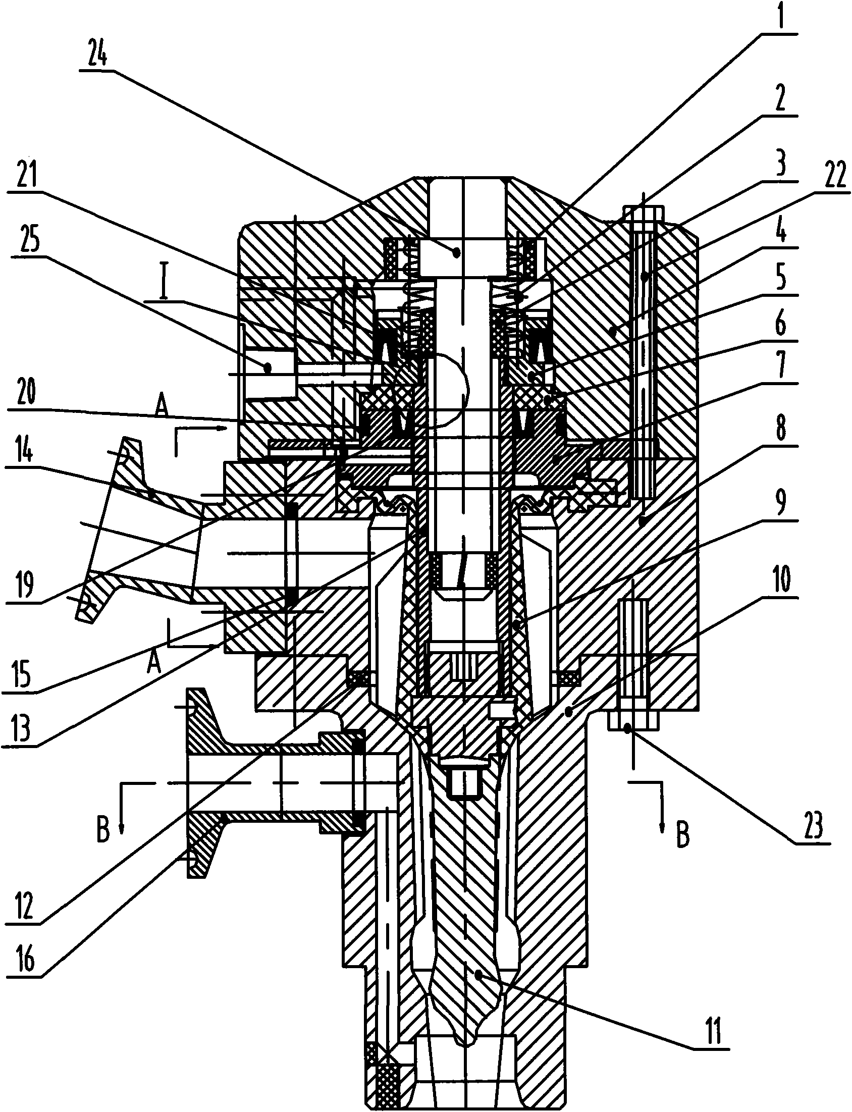
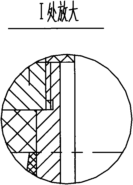
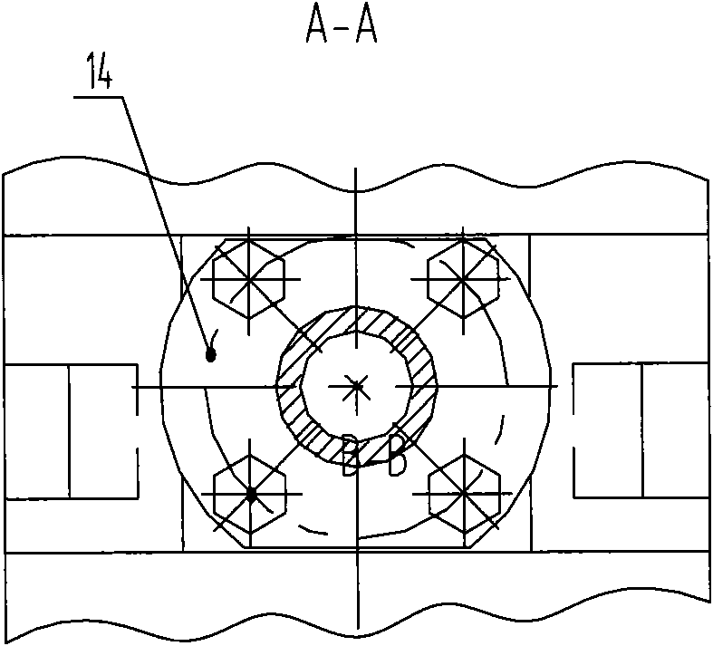
[0047] As shown in Figure 1, the aseptic filling valve is mainly composed of three parts: the upper valve seat 4, the lower valve seat 8 and the diversion sleeve 10. Inside the upper valve seat 4 is the opening and closing valve mechanism. The buffer ring 1 can play the role of buffering and anti-collision when the control gas is connected to open the filling valve; the spring 2 is compressed when the valve is opened. When the control gas is cut off, the spring 2 Reset to form a closed valve; the connecting sleeve 5 and the guide sleeve 13 are movable parts, so they need to be sealed with pneumatic U-rings 19 and 21. In order to facilitate the replacement of the pneumatic U-rings 19 and 21, the connecting sleeve 5 is designed as In the form of threaded connection, it is only necessary to unscrew the bolt 22, unscrew the connecting sleeve 5 and the guide sleeve 13 to replace it conveniently, without involving the gas-liquid separation membrane 9, so as to ensure that the gas-liq...


PUM


Abstract

The invention discloses a sterile filling valve applied to a sterile cold filling production line of beverage products. The filling valve comprises a material flowing cavity channel, and a valve opening and closing device is combined with a valve body into a whole, and the valve opening and closing device and the valve body are completely separated into two parts by an air and liquid separation film. The design guarantees the sanitation requirement of the sterile filling, and reduces the interference on the material flowing by the complicated design, so the material is favorable to flow, and the cavity channel is convenient to clean in all directions. The filling valve is integrally arranged on a mounting hole of a rotary table of a filling machine, and pairwise pressed by press plates, sothe valve can be conveniently mounted and detached. A pipeline of the filling valve is provided with an electromagnetic flow meter and a metal film valve for accurately controlling the filling accuracy. The valve adopts the filling method of not contacting bottle openings, so the pollution can not be caused even if the polluted bottles exist. Various functions of accurate filling of various levels, filling under the condition of bottle existence, no filling under the condition of no bottle, filling stop under the condition of bottle fulfillment, and the like can be realized by a filling control unit.

Description

technical field [0001] The invention relates to the field of beverage filling, in particular to an aseptic filling valve, which is especially suitable for the aseptic cold filling process of beverages such as fruit juice, tea and functional health-care beverages. Background technique [0002] Juice, tea and functional health drinks have always been loved by the common people. With the improvement of the living standards of urban and rural residents in China, people's consumption begins to advocate and pursue naturalness. Green and environmentally friendly aseptic cold-filled juices, teas and other beverages can compare with fresh fruits, so they have become the first choice for people to consume. The currently widely used hot filling process technology can effectively eliminate harmful substances in materials at high temperatures, and at the same time prevent a large amount of viscous substances such as sugar and tea polyphenols in beverages from being precipitated, which is...

Claims


Application Information

Patent Timeline
Patent Type & Authority Applications(China)
IPC IPC(8): B67C3/26B67C3/28B67C7/00
Inventor 管金岳史敏炜吴中军许蔷杜健徐聪玉孙建跃陈能玉
Owner 南京轻机包装机械有限公司
Why Eureka
Try Eureka