Method and device of combined process for producing ethylene by ethanol dehydration and catalytic cracking

A catalytic cracking and ethanol dehydration technology, which is applied in catalytic cracking, cracking, organic chemistry, etc., can solve problems such as difficult to achieve large-scale, affect process economy and competitive advantage, and achieve the elimination of flow control valves and solve the need Effects of thermal issues, process control simplicity

Active Publication Date: 2010-03-03
CHINA PETROLEUM & CHEM CORP +1
View PDF1 Cites 13 Cited by
  • Summary
  • Abstract
  • Description
  • Claims
  • Application Information

AI Technical Summary

Problems solved by technology

Judging from the currently adopted process route, it is difficult to achieve a large-scale ethanol dehydration reaction process, whe

Method used


Image

  • Method and device of combined process for producing ethylene by ethanol dehydration and catalytic cracking
  • Method and device of combined process for producing ethylene by ethanol dehydration and catalytic cracking

Examples


Embodiment approach 1

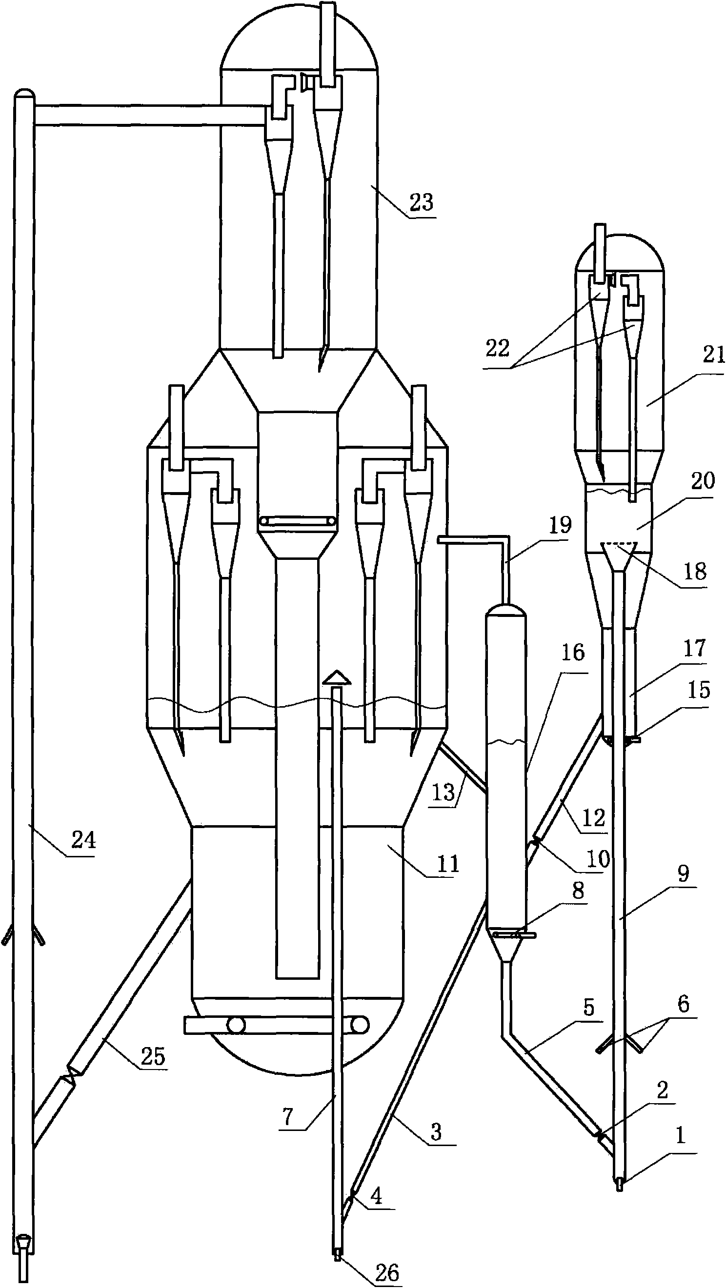
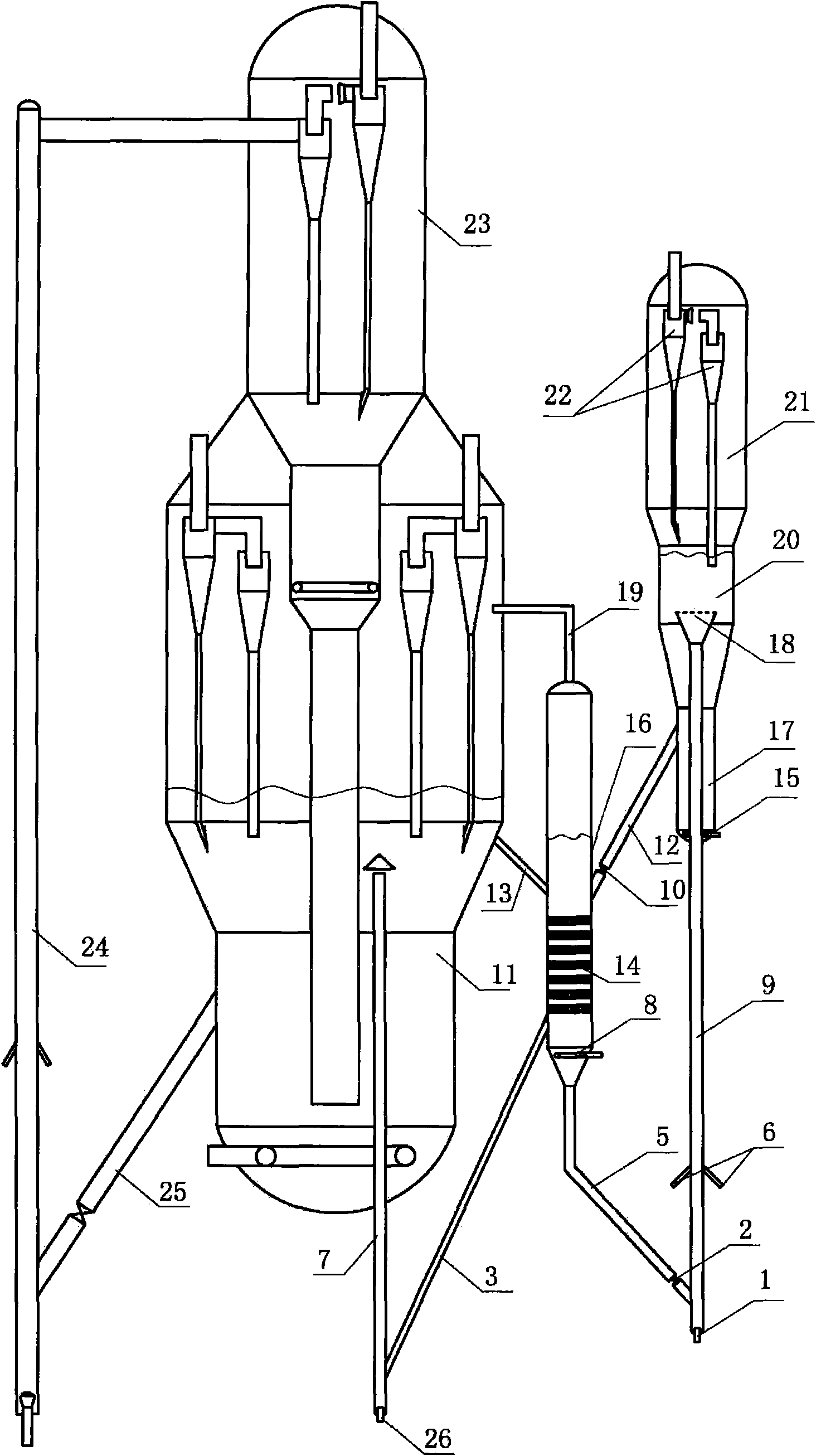
[0041] The high-temperature catalyst in the catalytic cracking regenerator 11 enters the middle and upper part of the dense-phase bed in the catalyst mixing tank 16 through the communication pipe 13, accepts the water vapor stripping injected into the mixing tank by the stripping medium distributor 8, and removes the entrainment of the regenerated catalyst. The superficial linear velocity of flue gas and stripping steam is 0.01-0.5m / s, preferably 0.05-0.45m / s, and the stripping time is 0.5-600s, preferably 1-500s. The stripped high-temperature catalyst is mixed with the catalyst injected from the delivery pipe 12, and the weight ratio of the two streams of catalyst is 1:2-30, preferably 1:3-25. After mixing, the catalyst is divided into two parts, large and small, and a small part of the catalyst is regenerated by the regenerator 11 through the delivery pipe 3 and 7. The delivery pipe 3 is provided with a flow control valve 4, and the delivery pipe 7 is directly connected to th...

Embodiment approach 2

[0045] The difference from Embodiment 1 is that the two catalyst inlets of the catalyst mixing tank are arranged horizontally, and an internal member 14 is arranged in the catalyst mixing tank. At this time, the high-temperature catalyst and the low-temperature catalyst are first mixed and then stripped, avoiding the 700°C high-temperature catalyst and Hydrothermal deactivation of catalysts induced by water vapor exposure. In this embodiment, the outlet of the delivery pipe 7 is located in the dense-phase bed of the regenerator, and there is no catalyst flow control valve on the delivery pipe 7. At this time, the catalyst flow rate entering the regenerator is controlled by adjusting the amount of air injected by the nozzle 26. . In the catalyst mixing tank, the apparent linear velocity of the stripping steam is 0.01-0.5 m / s, preferably 0.05-0.45 m / s, and the stripping time is 1-1200 s, preferably 2-800 s.

[0046] The remaining operations in this embodiment are the same as th...

Embodiment 1

[0049] Trials were carried out on a medium-sized riser unit operating in continuous reaction-regeneration. The reactor form adopts the riser + fluidized bed mode, and the inner diameter of the riser reactor is 16 mm, and the height is 6 meters. There is a fluidized bed reaction section above the outlet of the riser reactor, the inner diameter of the reaction section is 64mm, and the height is 0.3m. The catalyst mixing tank has a diameter of 70 mm and a height of 4 meters.

[0050] The regenerated catalyst with a temperature of about 700°C enters the catalyst mixing tank through the regenerated inclined pipe, and mixes with the low-temperature catalyst after the reaction. The mixing ratio of the high-temperature regenerated catalyst and the raw catalyst to be reacted is 1:4, and the temperature of the catalyst after mixing is 400°C. The mixed catalyst is in reverse contact with the water vapor injected from the lower part of the mixing tank to remove the flue gas mixed in the ...


PUM


Abstract

The invention relates to a method and a device of a combined process for producing ethylene by ethanol dehydration and catalytic cracking. The method comprises: placing an ethanol raw material and a catalyst in an ethanol conversion reactor to allow the ethanol raw material to contact the catalyst to react; separating the reaction product from the catalyst in a settler; delivering the reaction product to a post-separation system; stripping the catalyst by using steam in a stripping still; delivering the catalyst to a catalyst mixing tank to mix the catalyst with a catalyst from a catalytic cracking regenerator; and delivering one part of the mixed catalyst to the ethanol conversion reactor and delivering the other part the mixed catalyst to the catalytic cracking regenerator. The method adopts a gas-solid-solid circulating fluidized bed ethylene production process and combines the process with a catalytic cracking process, thereby solving the heat requirement problem of an ethanol dehydration reaction system, simplifying the fluidized bed ethylene production process, reducing equipment investment and contributing the easy realization of a large-scale process of ethylene production by ethanol.

Description

technical field [0001] The invention relates to a combined process method and device for ethanol dehydration to ethylene and catalytic cracking Background technique [0002] Ethylene is the basic raw material of many important chemical products (such as ethylene oxide, polyethylene, polyvinyl chloride, etc.). With the development of the world economy, the demand for ethylene is increasing day by day. It is estimated that by 2010, the global demand for ethylene will reach 140Mt / a. Due to the rapid growth of my country's economy, the annual growth rate of my country's ethylene demand exceeds the world average. The main source of ethylene is the steam cracking of petroleum hydrocarbon raw materials. In recent years, the price of crude oil has soared, which has caused the production cost of cracking ethylene to rise sharply. In addition, petroleum resources, as a non-renewable resource, are gradually being exhausted, so the development and utilization of renewable raw material...

Claims


Application Information

Patent Timeline
IPC IPC(8): C07C1/24C07C11/04C10G47/00C10G11/00
CPCY02P20/584
Inventor 侯栓弟杨克勇张占柱张久顺许克家常学良朱丙田李强
Owner CHINA PETROLEUM & CHEM CORP
Why Eureka
Try Eureka