Power transmission method and device for engineering machinery

A technology for power transmission devices and construction machinery, which is applied to transmission parts, mechanical equipment, transmission boxes, etc. It can solve problems such as high cleanliness requirements for lubricating oil, impact on the integrity of the transmission system, and space position effects, and achieve low noise , simple structure, and the effect of reducing lubrication costs

Inactive Publication Date: 2010-03-03
GUIZHOU QUNJIAN PRECISION MACHINERY
View PDF4 Cites 5 Cited by
  • Summary
  • Abstract
  • Description
  • Claims
  • Application Information

AI Technical Summary

Problems solved by technology

[0004] The current power transmission method affects the integrity of the transmission system due to the use of two independent parts, the main gearbox and the auxiliary gearbox. In addition, when installing the auxiliary gearbox located under the sub-frame of the chassis, it will still be affected by the space position. Influence, installation is very troublesome, not easy to install and operate
Due to the long route of power transmission in the vertical direction, in order to ensure the connection with the main gearbox above the sub-frame of the chassis, the sub-gearbox adopts a multi-stage cylindrical gear transmission method, which has complex structure, large number of parts, high manufacturing cost and low transmission efficiency. Problems with low and high operating noise
In this multi-stage cylindrical gear transmission mode, the lubrication of gears and bearings can only be lubricated by oil injection, which not only requires the design of an additional complex lubrication system, but also requires a high degree of cleanliness of lubricating oil

Method used


Image

  • Power transmission method and device for engineering machinery
  • Power transmission method and device for engineering machinery
  • Power transmission method and device for engineering machinery

Examples


Embodiment Construction

[0020] The present invention will be described in further detail below in conjunction with the examples, but not as a limitation to the present invention.

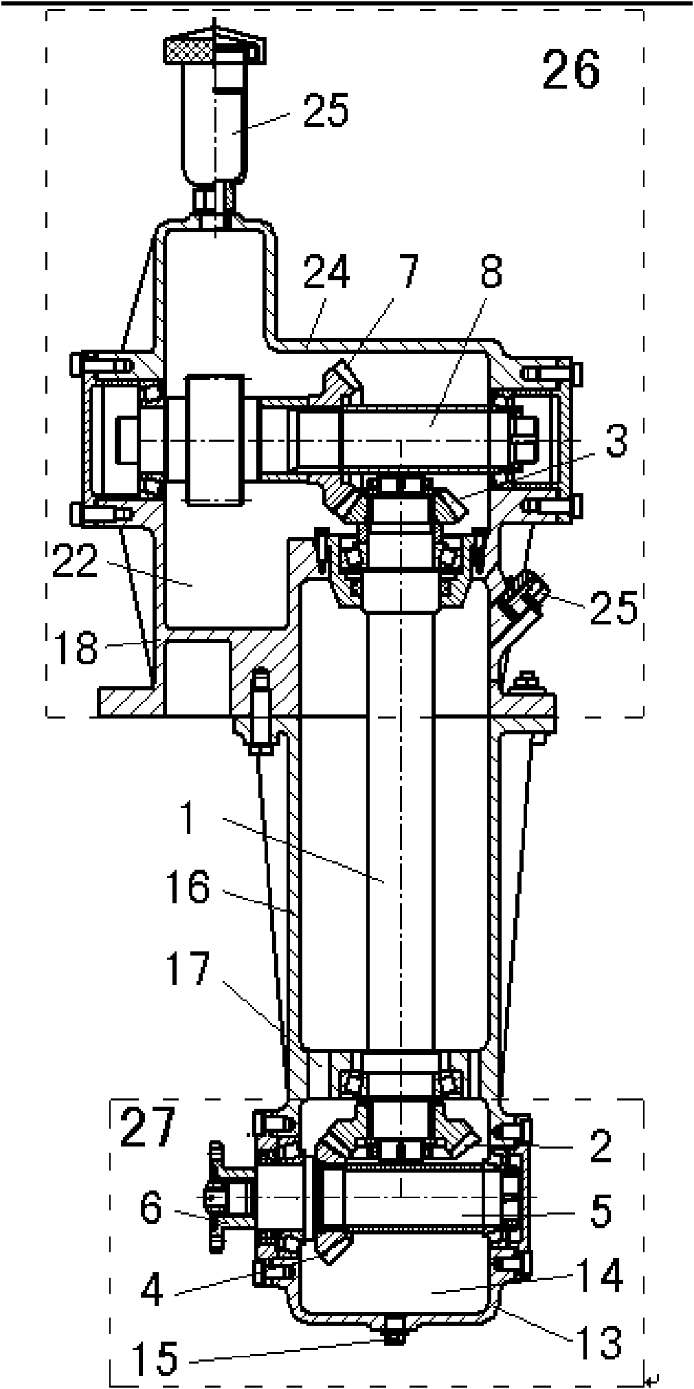
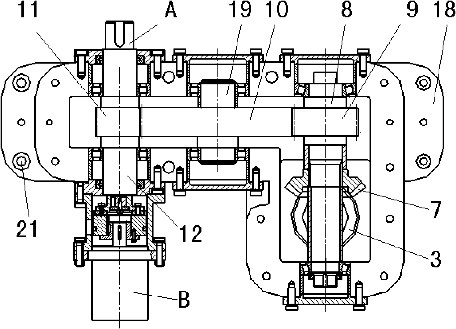
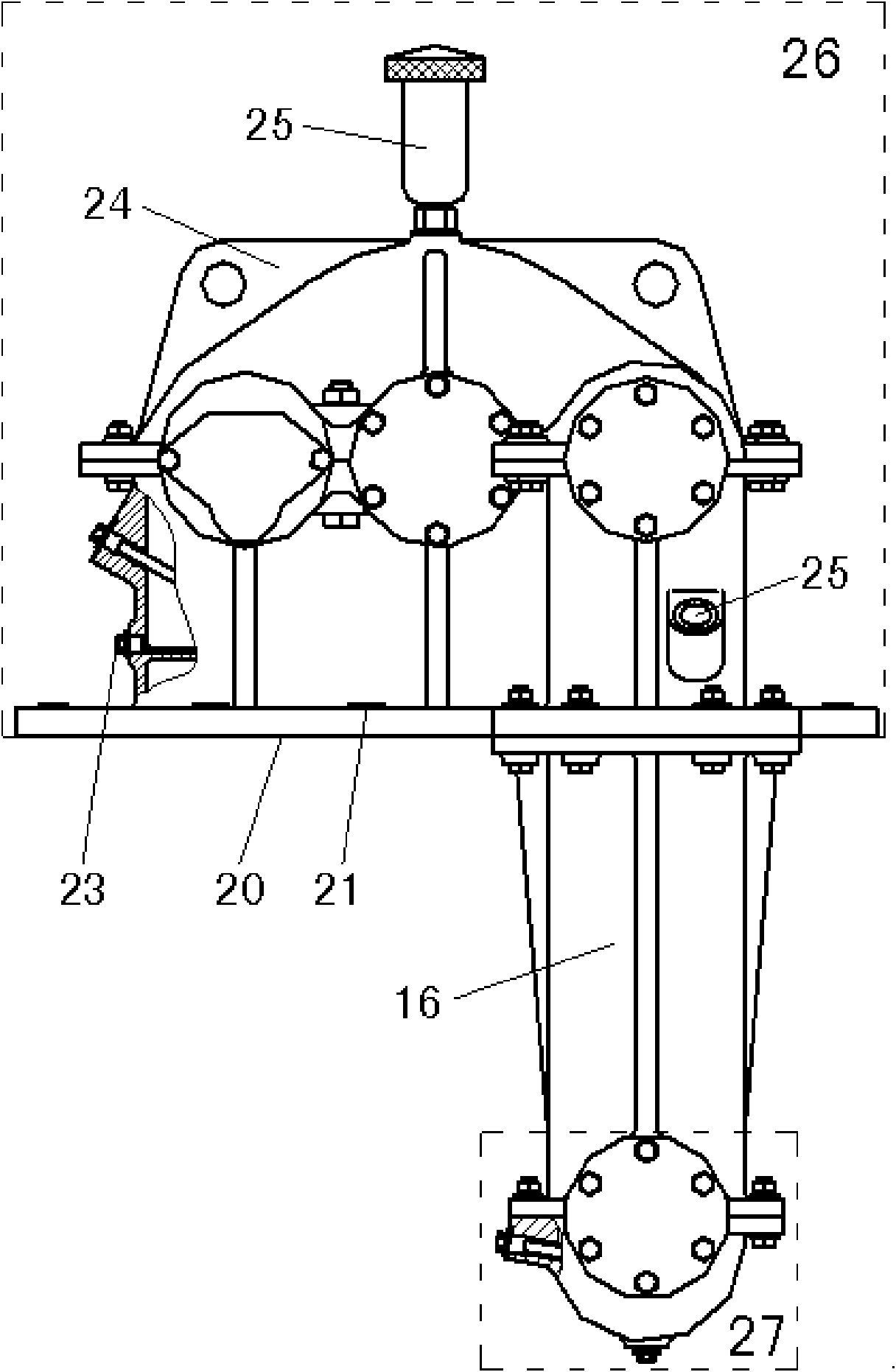
[0021] Embodiments of the invention. A power transmission method for construction machinery, such as figure 1 , figure 2 and image 3 shown. In this method, the input interface provided on the lower casing 13 is connected as a whole with the dual-function interface A and the output interface A arranged on the upper casing 18 through the middle casing 16; The input power is redirected by the pair of bevel gears, and the power is transmitted to the upper casing 18 through the long shaft 1 set in the middle casing 16, and the power from the long shaft 1 is redirected through a pair of bevel gears in the upper casing 18. , and through the driving gear 9, the transition gear 10 and the driven gear 11, the two ends of the driven gear 11 are used as the dual-function interface A and the output interface B respectively. The ...


PUM


Abstract

The invention discloses power transmission method and device for engineering machinery. In the method, an input interface arranged on a lower casing is connected with a dual-function interface and anoutput interface which are arranged on an upper casing through a middle casing; the input interface changes the direction of input power through a pair of bevel gears arranged inside the lower casingand transfers the power to the upper casing through a long axis arranged inside the middle casing, and changes the direction of the power from the long axis through a pair of bevel gears in the uppercasing; the speed of the power is changed through a driving gear, a transition gear and a driven gear; and both ends of the driven gear are respectively used as the dual-function interface and the output interface. The device is an integrated gear reducer which can ensure the integrity of a transmission system and is L shaped, thereby being convenient for installation. The device has the advantages of simple structure, less quantity of used parts, low manufacturing cost, high transmission efficiency, stable operation and low noise. The device can adopt a simple lubrication mode during operation, thereby reducing the lubrication cost.

Description

technical field [0001] The invention relates to a power transmission method and device, in particular to a power transmission method and device for engineering machinery. Background technique [0002] A dual-frequency motor, a hydraulic oil pump, an engine and a gearbox are installed on the construction machinery, and the power of the engine is output by the power take-off on the gearbox. In order to transmit the power of the engine to the dual-frequency motor and the hydraulic oil pump, a power transmission device is required. The power transmission device should have an input interface connected to the power take-off, an output port and a dual-function interface respectively connected to the hydraulic oil pump and the dual-frequency motor, and the installation positions of the components in the existing construction machinery cannot be changed. On construction machinery, the power take-off of the engine power output interface is located between the gearbox, transfer case ...

Claims


Application Information

Patent Timeline
Patent Type & Authority Applications(China)
IPC IPC(8): F16H57/02F16H57/04F16H57/023
Inventor 石年平
Owner GUIZHOU QUNJIAN PRECISION MACHINERY
Why Eureka
Try Eureka